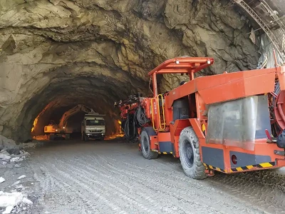
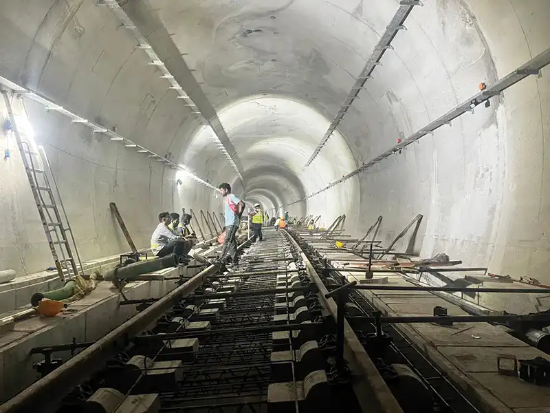
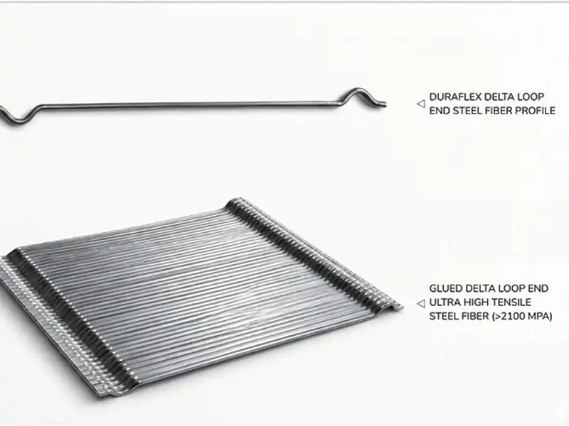
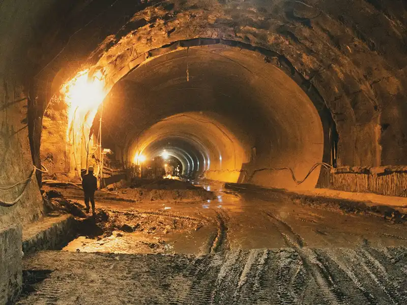
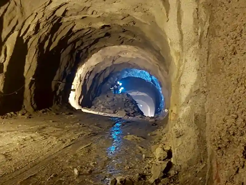
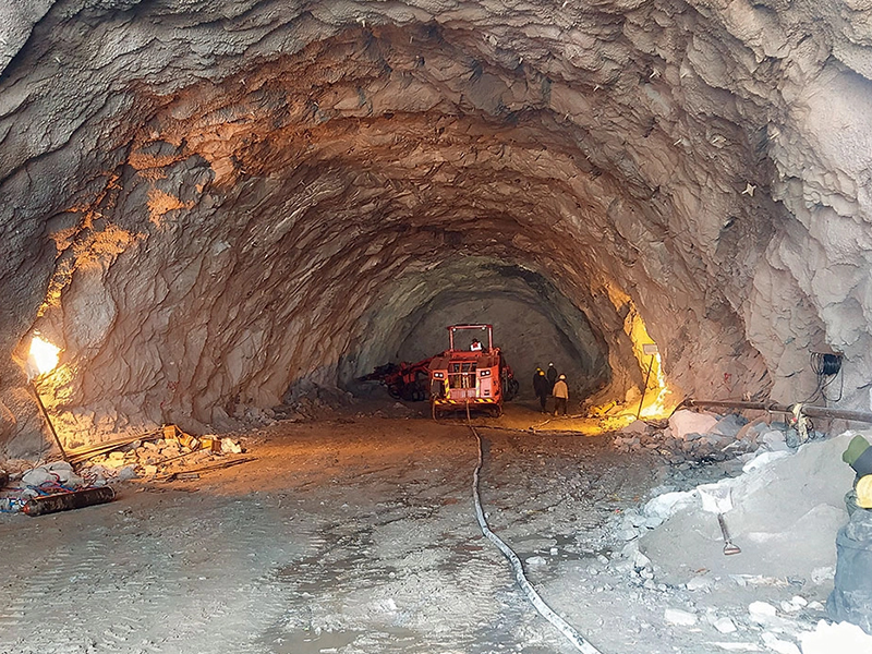
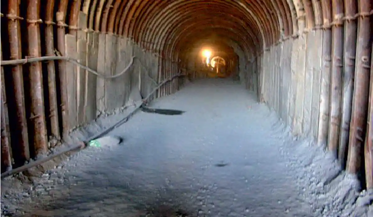
Construction of Head Race Tunnel for Sewa Hydroelectric Project (Stage-II) LOT SW-1

Published on:
03 November 2021
Published in: NBM&CW November 2021
Share:
We Value Your Comment