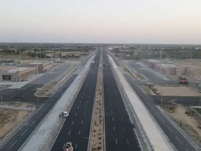
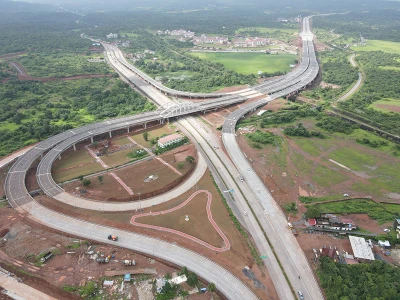
The Delhi-Vadodara Expressway is a part of the most anxiously awaited Delhi-Mumbai Expressway - the foundation stone for which was laid on March 8th 2019. Also referred to as the Delhi-Mumbai Industrial Corridor, it is planned as part of the Bharatmala Pariyojana. With a total length of around 1350km, it passes through six states - starting from Delhi to Maharashtra via Haryana, Rajasthan, Madhya Pradesh and Gujarat (Fig. 1).

Initially, an 8-lane wide expressway will be constructed with reserved space in the middle of road for expanding it to 12 lanes. Once completed, the travel time between Delhi to Mumbai will reduce from the present 24hrs to 12hrs. For construction purposes, the total length of the expressway is divided into 4 sections and each section is then divided into small packages. At the Delhi end, the expressway has two main entry and exit points: first at DND (Delhi Noida Direct) flyway in Delhi and the other at Alipur village, north of Sohna (near Gurugram) in Haryana. Traffic entering from both points and moving towards Mumbai will merge at the double trumpet interchange with KMP (Kundli-Manesar-Palwal) expressway at Khalilpur village in Nuh district of Haryana. Brief details of all four sections are given below:

Section 02: (Sohna-KMP-Vadodara): This section is 844km long (longest section of this expressway) and is divided into 31 small packages. Out of 31, 3 are in the state of Haryana covering a length of 79km, 13 are in the state of Rajasthan covering 373km, 9 are in Madhya Pradesh covering 244km, and 6 are in Gujarat covering 149km. This section starts at Sohna Gurugram road at Alipur village and ends at Ahmedabad interchange at Dodka village in Vadodara district. The starting of this section is the 2nd entry exit point of Delhi end.
Section 03: (Vadodara-Virar): This section is 354km long and is divided into 13 packages. Out of 13, 10 are in the state of Gujarat covering a length of 277km and 3 are in the state of Maharashtra covering the remaining 79km length of this section. It starts from Ahmedabad interchange at Dodka village and ends at Virar in Palghar district, Maharashtra.
Section 04: (Virar-JNPT): This section is 92km long and is divided into 5 packages. All 5 packages are in the state of Maharashtra. It starts from Virar in Palghar district and ends at JNPT (Jawaharlal Nehru Port Trust) Raigad district, Maharashtra.
The Section 2 of the project is referred to as the Delhi-Vadodara expressway and is currently partly open for traffic, specifically between Sohna to Dausa near Jaipur, Rajasthan.
This paper provides an overview of the first package of this section, which covers 18.461km length. It starts from Sohna-Gurugram road at Alipur village and ends just before the KMP expressway junction. There are a total of 23 structures (excluding culverts) constructed in this package. It includes 9 VUPs (vehicular underpass), 3 SVUPs (small vehicular underpass), 2 LVUPs (light vehicular underpass), 5 minor bridges, 1 major bridge, 1 flyover, 1 interchange and 1 ROB (rail over bridge) cum viaduct. Two independent carriageways are provided for traffic movement in each direction and the overall deck width for structures is kept as 21.25m for each carriageway. Both carriageways are separated by a clear median gap of 12.5m, which will be used for increasing the number of lanes in the future.
A 3060m-long elevated viaduct is one of the major structures of this package. This viaduct crosses two major junctions on surface level road, railway track of dedicated fright corridor and one canal along its length. For movement of local traffic between the two junctions of surface level road, a service road is provided under the viaduct on median side. In general, 3 span continuous modules with each span of 30m length are provided. However, at obligatory locations 60m spans are proposed. For crossing the railway line of dedicated fright corridor, 72m long bow string span is provided.
There are a total 175 spans (total for both carriageways) of length 30m, for which PSC pretensioned I-girder with cast-in-situ deck slab and diaphragm is proposed as superstructure. The superstructure is made continuous through deck continuity and is supported over spherical bearing provided below the diaphragm. The bearings are proposed below the diaphragm so that girder casting can be started without waiting for bearing/bearing sleeves. For deck width of 21.25m, 6 precast pre-tensioned girders are provided at 3600mmc/c spacing across traffic direction, with 1625mm long cantilever slab on each side. For casting of around 1200 pre-tensioned I-girders, 5 pre-tensioning beds were developed with casting facility of 4 girders on each bed. The approximate time cycle for casting of girder was 7 days. Depth of pre-tensioned girders is kept as 2100mm and are prestressed by using 15.2mm low relaxation strands. Number of strands vary from 38 to 42 depending on girder position i.e. end girder or intermediate girder and loading condition.
Special vehicle loading is considered in the design along with all possible combinations of live load as per IRC:6-2017. The girders are supported over inverted-T shaped 19m long cantilever prestressed pier cap (Fig 2). 2900mm deep PSC pier cap is comprised of two distinct components, first 3500mm wide & 700mm thick flange, which serves as the supporting platform for both permanent/temporary bearings and girders. Second component of cap is 2200mm high & 900mm wide web, in which all prestressing cables are placed. For design purposes, transversely pier cap is designed as prestressed inverted T section, while in the traffic direction flanges are designed as ledge beam supported on web.

At 13 obligatory locations simply supported 60m long steel concrete composite girder & slab type superstructure is proposed (Fig 3). The depth of steel girder is kept as 2900mm at mid span and is reduced to 2100mm near support, in order to match depth with PSC girder of 30m span. This avoided the requirement of step wall on pier cap. Approximate 360t of structural steel is used in one span of 60m length, having 6 longitudinal girders, 3 intermediate and 2 end cross girders. Initially, it was proposed to divide the 59.1m long steel girder into three segments of length 23.55m+12m+23.55m for erection purpose. The two end segments measuring 23.55m in length were to be erected with one end of girder supported on pier cap and other on temporary support installed on the ground. The central 12m segment was to be erected on same temporary supports and was to be connected with other two parts with splice plate and bolts. However, the assembling of three segments was done on ground only and two complete girders coupled together were erected over pier cap with two high capacity cranes. From aesthetic point of view same shape of pier cap is adopted for 60m span as is adopted for 30m span, however depth of cap is increased from 2900mm to 3200mm. Both flange and web of pier cap were increased equally i.e. by 150mm. The 7 number of 19T15 cables are stressed in pier cap supporting 30m spans and 8 number of 19T15 cables are stressed in pier caps supporting 60m span. Stressing of these cables is carried out in 3 stages. The first stressing is done after casting of pier cap, and is primarily to support the self-weight of pier cap and weight of PSC girders. The second stage stressing is carried out after erection of PSC girders from spans on either side of cap and casting of diaphragm. Final stage stressing is done after casting of cast-in-situ deck slab. The height of viaduct (Formation level to existing ground level) varies from 6m (near A1 abutment) to 20.5m (near DFC crossing). Circular piers are with diameter varying from 2000mm to 3500mm depending upon height are provided. The soil profile in the entire stretch of viaduct consists of silty sand with gravels. Based on Geotech investigation report and recommendations 1200mm diameter bored cast-in-situ piles of length 25m, having safe load carrying capacity of 460t are proposed. Pile group consisting of 6, 8 or 9 piles connected at top with pile cap of thickness 1900mm to 2300mm is proposed below each pier.

For crossing over dedicated fright corridor, 72m long and 21.25m wide bow string girder is proposed (Fig 4). Height of bowstring at mid span is kept as 12.5m. Two-legged portal pier are provided on each end of bow string girder, such that bearings are directly supported over column. The 4 Number of spherical baring are provided under each span. Each column has a plan dimension of 2000mm x 3000mm (3000mm along the traffic direction) and is supported on 6 Nos of 1200mm diameter, 26m long bored cast-in-situ piles under each column. Two pile caps, one below each leg of portal is connected to the other by means of 3 ties beams of size 500mm x 500mm, which is provided at middle of 2550mm deep pile cap.

There is one entry and one exit ramp for the viaduct having deck width of 9m. At the location of ramps, the alignment is having curvature of 1900m. In order to keep piers of ramp in the shadow of main carriageway piers, span length for ramp on outer side of curve is kept as 30.5m and on inner side of curve as 29.5. Three precast pre-tensioned girders are proposed in each span supported over RCC pier cap. Completed view of viaduct is shown in Fig 5.

The interchange structure is proposed at the start of project to develop a signal free junction with Sohna Gurugram road (Fig 6 to Fig 8). Interchange consists of 405m long curved elevated road, with 110m sharp radius, two VUPs of clear span 15m with 46.25m and 83.5m length. The elevated road has two independent carriageways with total deck width of 10.5m and 19.75m. For the elevated road portion span arrangement consists of 8 spans of 24.4m length and 7 spans of 30m length. 30m span is proposed in the portion where alignment is straight (or almost straight), while 24.4m span are proposed in curved portion of alignment. For the superstructure of 30m spans PSC pre-tensioned I-girders with cast-in-situ deck slab are proposed, while for 24.4m curved spans PSC post-tensioned I-girders with cast-in-situ deck slab are proposed. Due to curved span, each girder has different length, and girders were cast and stressed at the interchange location only. The carriageway with deck width 19.75m, PSC post tensioned inverted T shape pier cap is proposed over RCC circular pier, while for 10.5m wide deck, RCC rectangular tapered pier cap is proposed over RCC circular pier. At interchange, 1200mm diameter bored cast-in-situ pile, 23m to 25m long with pile group of 6 & 8 piles is proposed as foundation system.

There is one flyover of 2 x 40m span, having skew angle of 30 degree, in which PSC post tensioned girders are provided are supported over rectangular and varying depth PSC pier cap. For VUPs, SVUP & LVUPs RCC box type structure is proposed.

The construction of this package is done by EPC contractor APCO Infratech and detailed design (structures) consultancy services is provided by B&S Engineering Consultants, Noida. The construction of this package is completed and the stretch (from Dasna to Dausa) has been open to public since 14th Feb’ 2023, and it is expected that the entire Delhi-Mumbai expressway will be ready by 2024.

The construction of these corridors brings substantial advantages to the local community. It not only generates employment opportunities during both the construction and maintenance phase but also offers significant economic benefits by reducing travel distance and time. Additionally, the resulting decrease in fuel consumption and CO2 emissions has a notable positive impact on the environment, offering significant ecological benefits.