
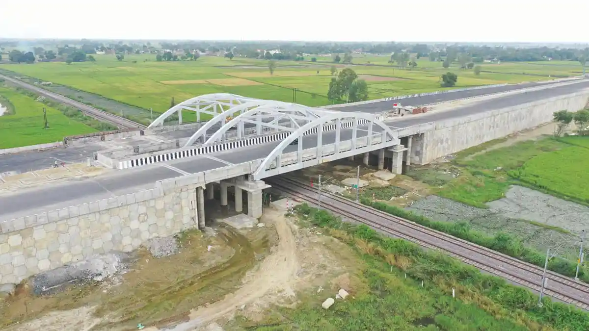
Er. Devjyoti Paul, Project Manager & Er. Harpreet Singh, Chief Project Manager, B&SEC, share the technical and construction features of three bowstring girder ROBs, recently constructed under Package I & III of Purvanchal Expressway in the state of Uttar Pradesh; the ROBs are of about 21.25m width, and span lengths of 52m, 58m and 64m c/c expansion joints.
Given India’s huge geographical area, smooth and efficient connectivity is key for its economic progress. With the vision to connect the remotest parts of the country with nodal centers, development of new highways and expressways are being done under various schemes. Whenever a highway/expressway is planned, it crosses existing or planned railway tracks at one or more places which necessitates the construction of ROBs.
A number of expressways are under construction in the state of Uttar Pradesh, namely, the 296-km long Bundelkhand expressway, the 91-km long Gorakhpur Link expressway, and the 594-km Ganga expressway. Beside these, the Yamuna expressway and the Agra-Lucknow expressway have been completed and opened for traffic.

The Purvanchal expressway, a project owned by the Uttar Pradesh Expressways Industrial Development Authority (UPEIDA), was recently inaugurated, and opened for traffic by the Honorable Prime Minister of India. The approx. 341km long expressway starts from Chand Sarai Village in Lucknow District and ends at Haidariya Village in Ghazipur District (Fig: 01).
The project is divided into 8 packages and awarded to different EPC contractors. The alignment of this expressway crosses railway tracks at 7 different locations and ROBs are constructed at each location. Out of 7 ROBs, 4 have bowstring girder type superstructure, while 3 have steel concrete composite girders. Of the 3 ROBs discussed here, (out of 4 Bowstring Type) two are in package-1 and one is in package-3.
The overall deck width of these structures is 21.25m for single carriageway. Two independent carriageways are provided for traffic movement in each direction, with separate bowstring girders provided to support the up and down traffic. In Package-1 the 52m bowstring ROB is situated at the start of expressway i.e. at Ch. 1+070 and the 58m bowstring ROB is situated at Ch. 31+064. In Package-3 the 64m ROB is situated at Ch. 120+675.
All the three ROBs have a similar structural arrangement. The main railway span, which is the bowstring girder span, is sandwiched between two small RCC slabs. In this paper 3-ROBs are referred as ROB-1, ROB-2 and ROB-3 for the main railway spans of 52m, 58m and 64m, respectively. The side spans are 10.545m for all the ROBs. These ROBs are supported on 4 spherical bearings provided below four corners of the main bowstring girder.
The substructure consists of RCC portal piers resting on bored cast-in-situ pile foundations. The portal pier type substructure consists of two main rectangular columns, provided directly below the spherical bearings, and three circular intermediate columns supporting 24m long RCC rectangular portal beam. RCC bearing inspection platforms, cantilevered out from the portal beams are provided in all the ROBs.

Although the bowstring girders were situated in seismic Zone-III as per IS-1893 Part-1 2016, still as an additional safety measure, seismic arresters are provided on the portal piers (Fig 03). All members, except the bottom crossbeams in the bowstring girder are built up steel box sections. The bottom crossbeam is built up steel I-section. The bottom chord of the bowstring is connected to the top arch by steel box hangers. By using box beams as hangers, frame action is introduced in transverse direction to increase lateral stability. 3 bottom crossbeams are placed between the consecutive hangers. 7 hangers are used in the 52m span ROB and 9 hangers are used in both 58m and 64m span ROBs. The distance between the consecutive hangers are 6.25m, 5.6m and 6.2m for ROB -1, 2 & 3 respectively.
Table1: Comparison of Structural Arrangement | |||
Parameters | ROB-1 | ROB-2 | ROB-3 |
a) Superstructure | |||
Package of E’way | Package-I | Package-I | Package-III |
Main Span | 52m | 58m | 64m |
Side spans | 10.545m | 10.545m | 10.545m |
Rise of Arch | 10m | 11m | 12m |
No of Hangers | 7 | 9 | 9 |
Distance between Hangers | 6.25m | 5.6m | 6.2m |
Bottom Chord | 1.2m x 0.8m (25mm thk. Plate) | 1.2m x 0.8m (28mm thk. Plate) | 1.2m x 0.8m (28mm thk. Plate) |
Top Arch | 1.2m x 0.8m (32mm thk. Plate) | 1.2m x 0.8m (36mm thk. Plate) | 1.2m x 0.8m (36mm thk. Plate) |
Hanger | 0.864m x 0.5m (32mm thk. Plate) | 0.864m x 0.6m (32mm thk. Plate) | 0.864m x 0.6m (32mm thk. Plate) |
Bottom Cross Beam | 1.056m to 1.325m (36mm thk. Max. Plate) | 1.056m to 1.325m (36mm thk. Max. Plate) | 1.056m to 1.325m (36mm thk. Max. Plate) |
b) Substructure | |||
Foundation type | 1200mm dia. 30m long bored cast in situ pile | 1200mm dia. 30m long bored cast in situ pile | 1000mm dia. 25m long bored cast in situ pile |
No of Pile below each side | 14 | 14 | 16 |
Depth of Pile Cap | 1.8m | 1.8m | 1.75m |
Portal Column dimensions | 2.5mx1.5m | 2.5mx1.5m | 2.5mx1.5m |
Intermediate portal columns | 1500 dia. | 1500 dia. | 1500 dia. |
Clear height of Portal Column | 9.046m | 7.166m | 6.708m |
Portal Beam Depth | 1.25m | 1.25m | 1.5m |
Table 2: Comparison of Structural Steel Quantities | |||
Parameters | ROB-1 | ROB-2 | ROB-3 |
Kg/sqm | 590 | 680 | 665 |
Total Tonnage | 690T | 890T | 950T |
The ROBs were fabricated as fully welded structures, with no bolted connection. For ROB-1 and ROB-2, the bowstring girders were fabricated at a fabrication shop in Ghaziabad and transported to the site in pieces. Similar methods were adopted in the erection of ROB-1 & ROB-2. For ROB-1, bare frame of the bow string girder was assembled on ground at site and was lifted and towed by hydraulic jacks on the already constructed substructure and portal piers. 4 hydraulic jacks with 300MT pulling capacity were used to pull the bowstring girder weighing approximately 690T. ROB-2 was assembled at required level on temporary supports, to avoid lifting operations.
As erection of the bowstring girders had to be completed over operational electrified tracks of the Indian Railways, traffic closure blocks were taken from the Railways from a safety point of view. Traffic block time was granted by the Railways in 5 slabs, totaling to 17 hours for ROB-1 and whole operation of the erection and inspection by RDSO was completed within this time frame. As the time for completion of the erection activity was very less, minute and accurate planning was done by the contractor Gayatri Projects. After putting the bare frame in place, the corrugated profile sheets were installed for concreting the deck slab. Construction stage activities are shown in Fig. 04 to Fig. 09. Submerged Arc Welding (SAW) was used in the fabrication shop and Shielded Flux Core Arc Welding (FCAW) was done at site for the splice connections.

For ROB-3 in Package-III, 18 temporary trestles were erected on ground with temporary RCC foundations for supporting members of the bowstring ROB of each carriageway. The trestles were placed as per the clear distance requirements of the Standard Schedule of Dimensions (SOD) of Indian Railways. During erection, the bottom level of the bearing was kept 1.0m higher than the actual level to facilitate checking and inspection. Upon inspection by RDSO, the bare frame of the ROB was lowered and placed on the permanent bearings by using 4 hydraulic jacks of 500T load carrying capacity each. Like the other ROBs, no bolting was used. Fig. 09 shows the construction stage activity for ROB-3. Upon completion of bare-frame structure, deck concreting was done followed by crash barriers and surfacing.
Design Criterion & Approval
The ROBs were designed as per IRC: 24-2001, IRC: 22-1986, IS: 800-1984, IRC: 6-2014 stipulations. 6 lanes of live load with congestion condition and special purpose vehicle of 385T load was considered in the design, and design was governed by LL with congestion condition.
The ROBs are situated at site with basic wind speeds of 47m/s and seismic zone-III as per IRC: 6-2014 and IS:1893(Part-1) - 2016, respectively. The steel frame of the bowstring girders was designed as per the Working Stress Method (WSM) given in IS: 800-1984 and IRC: 24-2001. The foundation and substructure of the ROBs were designed as per IRC: 78-2014 and IRC:112-2011. E350 grade structural steel conforming to IS:2062-1986 was used in the fabrication of all the ROBs.
The main steel frame of the ROB was analyzed for various static conditions. For example, during construction of the deck slab it would behave as a bare steel frame but once the deck achieves strength, composite action would come into picture. For construction stage, only stiffness of the bare frame was considered. During construction stage checks, lateral torsional buckling of the bottom crossbeam was found to be critical, hence, intermediate cross bracing was provided to reduce the unbraced length of compression flange of the bottom crossbeam.
or SIDL loads, long-term stiffness of the composite steel frame was taken whereas for LL, WL and seismic loads, short-term stiffness of the composite steel frame was considered. Complete 3D modelling of the superstructure was done for analysis of the ROBs.
Structural design of substructure and foundation was carried under by limit state methodology. Portal frame structure was modelled in Staad Pro with pile foundation. For considering soil structure interaction, equivalent spring supports were provided along the length of the pile. Structural design, crack width checks etc. were carried under appropriate load combinations of SLS and USL as defined in IRC 6.
Superstructure is checked for deflection criteria under serviceability limit state, which came out to be the most critical check. Pre-camber is provided in both the main girder and crossbeams to offset the deflection due to permanent loads.
The superstructure of the ROBs was checked by IIT, Delhi, and the approval on the structural design was obtained from RDSO Lucknow. The substructure and foundations were approved by Zonal Headquarters of the Northern Railways at New Delhi, after being proof checked by IIT, Delhi.
Acknowledment
Sincere thanks to the engineers at Gayatri Projects Limited, APCO Infratech, and Egis India Consulting, for providing vital information on construction activities and onsite photographs.
Credits
Client: UPEIDA, Lucknow
EPC Contractor: Gayatri Projects, Hyderabad (Pkz-1) & APCO Infratech, Lucknow (Pkz-3)
Authority Engineer: Egis India Consulting Engineers, Gurugram
Design Consultant: B&S Engineering Consultants, Noida.
References
- Indian Railways Year Book 2019-20, Ministry of Railways. Retrieved 17 March 2021.
- Roads in India, Wikipedia
- Article: “In Yogi’s UP, expressways are scripting a silent transformation” published in The Print
- UPEIDA website