Project Developer: Peninsula
Consultant: STERLING Engineering Consultancy Services PVT. LTD.
Sterling’s Project Team
General Manager: Dinesh Bhaud
Project Leader: Karan Sitapara
Draughtsman: Vinayak Bhogle, Nitish Kadu, Devendra Maurya
Inception: Vinayak Naik, Santosh Kadam

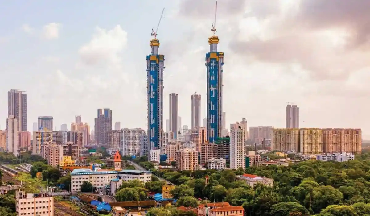
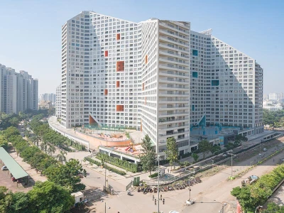
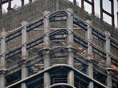
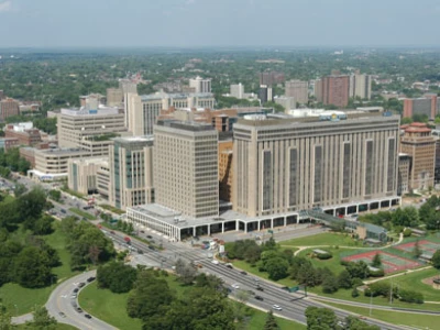
Work at the Salsette 27 high-rise residential project by Peninsula resumed after the lockdown restrictions were eased. On completion, Salsette 27 will add to the skyline of the city of Mumbai and will be viewed as yet another attractive landmark. A project may seem simple, but with changes in municipal by-laws and client/architect requirements, new challenges surface which require pioneering solutions.
The Salsette 27 is an eye-catching development in Byculla, Mumbai, overlooking the Mahalaxmi racecourse and the Haji-Ali dargah, both of which are unique to the city. The project has 2 basements, a ground floor, 7 podium levels, and 57 upper floors. The total height is 234 meters above ground level and the slenderness ratio of Salsette 27 towers is a shocking 9.6!
Amenities and features

Wind Tunnel analysis
Considering the height and slenderness, it was necessary to conduct a Wind Tunnel analysis of the towers to determine their realistic behavior with the surrounding development, wind intereference, and building shape. This was carried out by Australia-based wind engineering consultants, Wind Tech.
In this analysis, a physical 3D scaled model was prepared, replicating the exact mass, stiffness, and shape of the towers. The model was then studied by throwing wind at various speeds and intensities in a wind tunnel. The accelerations and displacements were recorded by a network of sensors placed on the model. All the recorded data was then processed to produce the wind forces which can be used while designing the towers.

Wind tunnel tests also provide accurate acceleration values near the top of the structure, which is extremely crucial in high-rise towers. Access acceleration in the towers may cause nausea or sea sickness in residents. The accelerations recorded for Salsette Towers were well under control as per the guidelines for human comfort levels.
Design Challenges
In a residential development project in Mumbai, it is always great news for a client when he receives additional FSI to construct additional floors. However in this case, much to the architects’ dismay, this news came after excavation was completed. The excavation was to accommodate a raft of 3-meter depth only, thus, the challenge was to design to accommodate the additional floor loads in the raft of this restricted depth. In addition to this, contractors had already mobilized at site a force of over 700 laborers. The cost of demobilizing or holding up the work would be very high; so, to make sure that the flow of work did not stop, the engineers had to work full throttle to issue the revised detailed design drawings on site. It was a race with the progress on site!
Additional floors overloaded the raft and caused additional punching shear. To cater to this, the walls in the basement were strengthened by increasing their thickness by 100 mm and increasing shear reinforcement in the raft. The raft had to be poured in three parts to control heat levels and each part was poured in layers of 300 mm.

An interesting occurrence on the site was the 140-ton per sqm bearing capacity, which is unusually high. To verify this, a footing load test was carried out. Contractors used a ground improvement technique, using a backhoe’s arm (commonly known as JCB), which they tapped on the surface to identify the soft areas which were to be excavated and filled with self-compacting concrete. Portions where the structure interacts with the soil are the most sensitive and must be given special attention as they are the ones most likely to lead to failures.
Software Tools
ETABS and SAFE software are great for modelling building behavior and generating fast and accurate results. In this project, the Sterling team used REVIT - a Building Integrated Modelling (BIM) tool. With all consultants working on one model, this tool boosts efficiency in collaborative planning and gives 3D renderings of the structure which overcome any shortcomings of 2D drafting. It models the structure in 3D, which allows the architects to identify any errors in his floor plans and sections. Sections and plans are developed automatically from the model which can produce output as a drawing file, thus reducing the workload on the draughtsman and reducing the probability of human error.
As mentioned earlier, the project gained additional FSI by providing parking area for an MCGM Pay and Park on two basement levels and the ground floor. A separate entrance is provided for the residents who can access the seven podium levels by ramps.
Structural Reinforcement
The towers house a couple of unusually deep girders on the top podium level, with support columns carrying loads of the 57 upper floors. There are two such 7-m deep girders in each tower. Reinforcement detailing of the girders was a challenge due to its complex stress distribution. Because of the depth these girders were acting as both beam as well as strut and tie system, which is a phenomenon usually employed in truss design. The girders are designed considering both beam action and strut-tie action. Its analysis is done using 8-noded solid shell elements in FEM based STAAD Pro software. Horizontal reinforcement near top and bottom of the girders are placed for resisting stresses as per beam action and diagonal rebars are provided to allow load transfer path as observed in 3D FEM analysis models. 16mm thick steel anchor plates are used to anchor the horizontal girder rebars to the supporting walls to avoid reinforcement congestion in the walls.

Jump Formwork

A Jain temple has been planned on the top of the podium. It requires some special regulations. The core of the temple known as the “Garbha Girha” had to be founded on soil and had to have a connection with earth. This required construction of a shaft filled with soil to support the temple, so that the requirement could be met. The soil shaft was designed similar to a lift well, which the engineers cleverly utilized as a structural member to support the podium floors.
The architects designed a grand temple which weighed 350 metric tons and required a construction joint to separate this concentrated mass from the podium structure.

Work at the project had resumed after the lockdown restrictions were eased. On completion, Salsette 27 will add to the skyline of the city of Mumbai and will be viewed as yet another attractive landmark. A project may seem simple, but with changes in municipal by-laws and client/architect requirements, new challenges surface which require pioneering solutions.