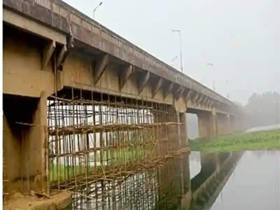
In a developing country like India, roads, rails and bridges are amongst the most important infrastructure assets that connect every corner of the country. Roads and bridges tend to undergo wear and tear with aging. When they get submerged, they are susceptible to further damages such as scouring, rebar exposure, corrosion, cavities etc. Hence, periodic inspection of bridges is essential to detect early deterioration and to schedule maintenance and restoration plans to prolong their life, prevent catastrophic damages, and loss of lives.

Typically, inspection procedures that are used conventionally are limited to areas of the structures which are easily accessible and safe to work. These inspections, which are majorly carried out by divers, have several limitations such as the depth that can be covered by the diver, accuracy, endurance, safety, etc.

This paper describes a comprehensive structural integrity assessment that Planys has tried and tested on the submerged regions of the bridge. Further a case study is also presented that highlights the work done by Planys team on a live project.
India has faced several bridge failures in the past such as the collapse of a foot over bridge in Mumbai, 2019, and the more recent bridge collapse in Gujarat in 2022. A recent analysis of the bridge failures in the country between 1977 to 2017 shows over 2130 bridge collapses. All these bridge failures take a heavy toll on life and property [1]-[4]. Maintaining safety and reliability of ageing civil infrastructure operating for several decades is of key importance to prevent catastrophic failures, especially after design lifetime is over, and during natural disasters. Standardized inspections at regular intervals help identify defects at their initial developmental stages, and therefore significantly reduce the overall repair and maintenance costs.
Current Technology for Bridge Inspections
Visual inspection is the first step in the evaluation of safety and reliability of assets. Key stages in the process of structural deterioration of concrete structures that may be identified by visual inspection include cracking, seepage, spalling, moisture ingress, beam delamination, exposed and corroding reinforcement [5] and subsequently, maintenance actions can be planned. However, visual modality of inspection is dependent on the expertise and knowledge of the investigator and it is ineffective when used alone, as it presents superficial structural information [7]. In order to obtain in-depth structural integrity information quantitative NDT techniques such as electromagnetic, acoustic and ultrasonic methods are preferred.
Ultrasonic pulse velocity (UPV) technique is among the most widely used inspection method for concrete structures owing to its portability and ease of applicability. The technique relies on the measurement of time of arrival of ultrasonic waves, T, traversing through the material of interest to calculate the pulse velocity, V, which is typically in turn correlated to the quality of the concrete. The pulse velocity is influenced in varying magnitudes by numerous factors including aggregate size, cement properties, reinforcements, member size, moisture, and member stress. Therefore, the UPV method can serve well as an indicator to identify zones of non-uniformity and as a prelude to advanced NDT investigation [8]. This technology is available in the market for superstructure structural assessments. For the substructure and the submerged portions, Planys has developed the technology indigenously and has successfully used it on projects to assess the structure integrity of submerged portions of concrete structures.
Structural durability of the reinforcement is significantly compromised by corrosion. For relatively newly constructed concrete with defined composition and structure, reinforcing steel is well protected against corrosion. However, concrete surface pH decreases with time and allows the threat of contamination with external chemical components that can penetrate the concrete and reach the reinforcement and induce accelerated corrosion. All submerged assets have several portions of their substructure in marine conditions which leads to further corrosion upon exposure. The corrosion process can be delayed by the use of certain types of concrete surface protection or employing low absorption concrete [9]. Many parameters including chloride content, sulphate ions, and concrete pH need to be evaluated in order to obtain a clear assessment of structural integrity [10].
ROV- Based Underwater Inspection Applications
Planys technologies has developed several technologies for underwater NDT, visual inspection and other surveys that have many use cases and applications in bridge inspections. Some of them are listed here:
- Visual Inspection to identify visual defects such as cracks, cavities, honeycombing etc
- Submerged piers and abutments
- Underdeck of the bridge
- Ultrasonic thickness gauging of the metal parts of the bridges, if any
- Underwater Concrete NDT
- Ultrasonic Pulse Velocity (UPV) for concrete structures
- Bathymetry and Side Scan Sonar Surveys
- Scour surveys using sophisticated SONAR technologies
The submerged portions of such civil structures, i.e., its substructures, are conventionally inspected by divers carrying payloads including cameras and lights. Inspection by divers pose human safety risks owing to unpredictable flow velocity, poor visibility, presence of debris and entanglement. Turbid or murky water presents a key challenge, limiting conventional manned inspection surveys to clear waters. Further, conventional scuba diver-based operations are also limited by the maximum sustained time and working depth which are typically 20 minutes at 20 m depth, 15 minutes at 30 m depth and 10 minutes at 40 m depth (ref: guidelines railways).
This proposed methodology for underwater inspection and NDT has various advantages such as mentioned below:
- The ability to inspect in dark and flooded areas
- Safe operations as human intervention underwater is nil
- Unlimited endurance
- Enhanced stability
- Reliable data acquisition with repeatability
- Lastly the AI enabled post-inspection analytical digital reporting dashboard (for auto- identification, quantification, enhancement and categorization of defects) also allows cross-comparison of inspection data recorded across multiple years and thus appropriately augments asset owners.
Case Study:
Inspection of road bridges in Maharashtra adapting the ROVs based substructure inspection and scour survey using 3D imaging SONAR
Planys conducted several road bridge inspections in multiple districts across the state of Maharashtra including few iconic bridges of national importance. These bridges are located on prime routes linking several important locations of the district and hence of significant importance to the state. The scope of work that Planys executed for these bridges included both visual inspection and scour survey of the submerged piers of the bridge.
ROV Based Inspection of Substructures
ROVs [11] are unmanned robots that can be designed to reach target immersed narrow and restricted locations and perform immersed structural inspection in the form of visual and non- destructive evaluation, and assessment of water quality. Further, the operation of ROVs has fewer limitations in terms of depth of operation, communication, and endurance as compared to human divers. Apart from such advantages, ROVs offer the possibility of streaming live data back to the control station (along with end user and surveyor), operation in hazardous conditions and high-speed on-board or on-site data processing capability.
Planys Technologies brings cutting-edge technology to address industrial problems, providing underwater inspection and survey solutions using indigenously manufactured submersible remotely operated drones. Indigenously developed technology has been widely acclaimed and accepted in numerous sectors in India and abroad including power, oil and gas, offshore and freshwater domains. Planys has completed 285+ projects in underwater inspection including 170+ bridge inspections using Remotely Operated Vehicles (ROVs).
The typical setup of the ROV and its subsystems are shown in Figure 1. The power is supplied to the command module, through which it is fed to the winch and then forwarded to the ROV. The command module and the tether winch are placed in a safe location above the bridge. The ROV is deployed through the top of the bridge or through a boat based on access points available at the site.

Figure 1: A schematic showing the overall setup for the ROV-based Bridge Piers inspection. ROV is equipped with high-definition cameras delivering a resolution of 1080p with 60 frames per second, as shown in Figure 2(a). Innovative technology to perform visual inspection even in extremely turbid water has been developed and used in inspection surveys. As shown in Figure 2(b), software-based video enhancement algorithms are used to compensate for quality loss in low light and turbid waters, such as to compensate loss of colour, contrast, or sharpness.

Scour Analysis Using 3D Imaging Sonar Technology
In extremely turbid (especially during monsoons) traditional underwater videography will not be possible to assess the orientation/spread age of scouring as the visibility is less than 10 cm.
Underwater 3D Imaging Sonars, also known as acoustic cameras, are used to replace video cameras in such cases. These sonars not only work in zero visibility conditions, but they also offer measurement solutions. They can hence assess and identify scouring, if any.
The sensor uses new high-resolution profiling Sonar technology to create an easy-to use underwater 3D Multibeam scanner. The sensor works much like a topographic laser scanner, using high frequency sound beams instead of lasers to create extremely detailed 3D imagery to collect measurement data with centimetre-level accuracy.
The 3D Imaging Sonar has a 360 degree spherical coverage as shown in the diagram. Its optimal range is 20m, as such, the subsequent scan will be taken within a 25-30m range of the current scan location to overlap data for creating an efficient mosaicking. Data obtained needs to be post-processed (data view is not real-time) and stitched to be made sense of using an OEM software. Post capture, 3D data requires playback, editing and post-processing, followed by mosaicking. Depending upon the site conditions, these processes can take up to several hours for each collected scan. Figure. 3 shows a mosaic created around one of the piers inspected and shows the different contour levels indicating scouring. The scour depth can also be measured by the technology to assess the severity of the damage.

Results and Discussion
ROV-Based Inspection of Substructures
Laser-based defect size estimation, metadata from the ROV including location, and depth at which the defect was observed, are overlaid onto the recorded live video feed. A sample defect image is given in Figure 4 showing three important features, 1. ROV twin lasers, 2. Size of the estimated defect, and 3. Position tagging of the defect on the bottom image. Custom designed underwater lights and camera system appended to the ROV’s turbid water inspection module recorded the following sample defects, from various bridge substructures presented, in Figure 5. Major defects including cavities, honeycombing and cracks were observed with enhanced visibility using the ROV’s turbid water inspection module.

This data overlay greatly enables localization as well as monitoring the growth of a defect and improves repeatability of results during a future operation; further, the feature can enable comparison and tracking of historical defect propagation status over a given period. Bright spots can be seen on the edges of the images given in Figure 5 (a) to (d). These are artefacts caused by total internal reflections within the turbid water inspection module.

Data Presentation and Reporting
The importance of presentation and reporting of data and critical sections, respectively, is often overlooked in a conventional structural assessment survey. The onus is often left to the end-user to examine large volumes of data with just numbers or video files. Further, in the case of periodic inspection of an asset, conventional data presentation methodologies do not allow locating or track key defects which can otherwise improve the confidence of decisions made following an investigative survey. The resulting examination becomes erroneous and makes the process of making important decisions about repair or maintenance of the structure under inspection very slow and challenging.
Planys Analytics DashboardTM
Planys Analytics DashboardTM (PAD) is an Intelligent AI-enabled Digital Analytics & Reporting Dashboard. It showcases compiled and analyzed data embedded into a highly interactive and user-friendly software interface depicting inspection locations with depth, position tagging, defects, key results and observations on a map. Further, AI-based analytics and enhancement tools extract meaningful insights and categorize them per industry standards. It is highly customizable and can integrate multiple assets on the same dashboard, making it very easy for high-level managers to take effective decisions.
Data collected at the bridge sites was further analyzed and presented on the Planys Analytics Dashboard. Data included videos from underwater visual inspection in turbid waters, underwater concrete UPV data points and complex SONAR data. All these results were tabulated and compiled on the user-friendly software interface depicting inspection locations, results and observations on a CAD model of the structure inspected. As a result, the dashboard reduced the interpretation time of the dam engineers by 95% and improved decision-making ability, and reduced costs by taking data-driven decisions for repair and maintenance.
Conclusions & Recommen- dations for Future Work
The paper presents one of the new technologies used for integrity assessment of the submerged portions of the bridges. The studies are carried out by various road and railway bridge asset owners. A methodology of integrity assessment of large structures using an approach which combines multiple techniques for inspection of substructures using unmanned submersible robotic systems was also presented. Key applications and use cases of a remotely operated underwater vehicle (ROV) are presented which is possible with the support of various sensors and tools for specific bridge health monitoring applications, including overall integrity assessment, sonar surveys, scour monitoring, and debris volume estimation.
Defect images, overlaid with metadata to enhance defect growth tracking and data repeatability, were also presented for the robotic inspection survey for the submerged part of the bridge. Overall structural integrity of the bridge was assessed after consolidation of data from both methodologies of the survey (Figure 6a). Numerous defects ranging from moderate to severe criticalities have been identified in substructures of the assets in the survey project presented. Further SONAR based scour assessment use case is also presented to understand different issues faced by bridges that is not obviously visible. This combined data is most useful in deciding the type and methodology of the repairs required for the bridge to enhance its serviceability, as well as extending the reduced life by strengthening measures based on accurate data where normal visual inspection of the underwater structure is not possible (Figure 6b).

Further, a comprehensive model to predict remaining life of the asset accounting numerous factors affecting structural health such as temperature, rainfall, or chemical composition of water and soil is under development.
References
- V. Sridhar, “Was it the bridge, or the bogies?,” Frontline - The Hindu, pp. 1–3, 2001.
- E. Online, “Foot overbridge collapses near CST station in Mumbai,” Economic Times, pp. 1–2, 2019.
- G. Mayuresh, J. Pankaj, S. Mustafa, and J. Sahil, “British-era Mumbai-Goa highway bridge collapses,” India Today, Mumbai, pp. 1–2, 03-Aug-2006.
- R. K. Garg, S. Chandra and A. Kumar, “Analysis of Bridge Failures in India from 1977 to 2017”, Structure and Infrastructure Engineering, Vol 18, Issue 3, pp 295-312, 2022.
- A. M. Alani, M. Aboutalebi, and G. Kilic, “NDT & E International Integrated health assessment strategy using NDT for reinforced concrete bridges,” NDT E Int., vol. 61, pp. 80–94, 2014.
- S. Kashif Ur Rehman, Z. Ibrahim, S. A. Memon, and M. Jameel, “Nondestructive test methods for concrete bridges: A review,” Constr. Build. Mater., vol. 107, pp. 58–86, 2016.
- F. C. Lea and C. R. Middleton, “Reliability of Visual Inspection of Highway Bridges,” 2017.
- K. Komlos, S. Popovics, T. Niirnbergeroh, B. Babd, and J. S. Popovics, “Ultrasonic Pulse Velocity Test of Concrete Properties as Specified in Various Standards,” Cem. Concr. Compos., vol. 18, pp. 357–364, 1996.
- D. P. Barkey, “Corrosion of steel reinforcement in concrete adjacent to surface repairs,” ACI Mater. J., vol. 101, no. 4, pp. 266–272, 2004.
- J. Hulimka and M. Kału, “Basic Chemical Tests of Concrete during the Assessment of Structure Suitability—Discussion on Selected Industrial Structures,” Appl. Sci., vol. 10, p. 358, 2020.
- A. J. Ashish, M. Galipali, V. Upadhyay, and K. Balasubramaniam, “A Novel Ultrasonic Inspection Methodology for Submerged Metallic Structures using a Remotely Operated Vehicle (ROV),” in ISNT JNDE, 2017, vol. 1, pp. 14–16.
- V. Upadhyay, S. Gupta, and P. Agarwal, “Multi-functional Remotely Operated Submersible Vehicle (ROV) System, Patent Application Number 201741022485,” 2016.
- “UCT 4600 - Ultrasonic Quality Assessment Technology For Concrete,” Roop Telesonic Ultrasonix Limited (RTUL), 2018. [Online]. Available: http://www.rooptelsonic.com/productlisting/ndt- equipment/concrete-tester.
- D. G. Stromberg, “New Advances in Underwater Inspection Technologies for Railway Bridges Over Water,” Railw. Track Struct., vol. 60606, no. 312, pp. 1–29, 2011.