
Gurpreet Singh Sohel, Senior Design Engineer, TCPL, New Delhi
The Omkareshwar Dam Project was conceived in 1965 as an irrigation and power dam to be built in the Central Indian State of Madhya Pradesh. The project entails the construction of a 73 meter high concrete gravity dam on the Narmada River about 1 km upstream of Mandhata Island, where the famous temple town of Omkareshwar is situated. At full reservoir level, the project will submerge 93 sq km including up to 5800 ha of forest lands and some 30 villages in the Khandwa and Dewas Districts of Madhya Pradesh. The dam is envisaged to provide up to 520 MW of electricity nd will irrigate 147,000 hectares.
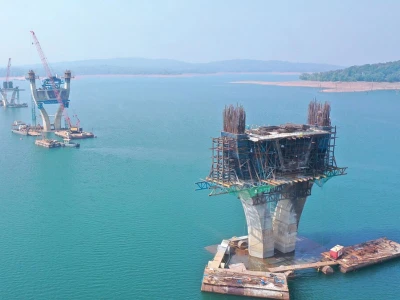
The broad scope of the project was to construct a spillway type Dam across river Narmada. It included the construction of power house for electricity generation (8x65 MW) and a bridge over the spillway to serve the functional & operational requirement of the spillway.
The Need of Bridge
To understand the requirement of bridge one must be aware of broad operations involved in working of dam. Figure 1 & 2 shows the key plan of the site showing location of the Dam and typical section of Dam respectively. The water reservoir created on upstream side of the dam to develop potential energy required for the generation of electricity was to extend in approx. 93 sq km of area. The excess water stored in the reservoir is required to be released from time to time for various reasons. The same is done through the under sluices or by spillway over the dam. The release of water is controlled by Stop-Logs and Trunion installed in between the piers. The Stop-Log is provided on upstream side of this dam (Figure 2) in between the piers on top of the dam.
The whole width of the dam was divided into 26 bays by piers P1 to P27. The bridge was required to be provided from piers P4 to P27 only. The Stop-Log installed between these piers operates with the help of Stop-Log Gantry Crane which rests on the bridge above the pier Figure 3.
The bridge was also required for launching of the trunion on the dam with the help of special cranes other than that required for stoplog operations.
Apart from all these special requirements bridge was also required for its most basic requirement i.e. bridging the two banks of the river.
The Proposal

Precasting was the only viable and economical answer to the present situation. It was proposed to precast beams as primary structural element of the superstructure to reduce the construction time to minimum. The following options were considered:
- First 7 spans (i.e. P4 to P11) with cast–in–situ type superstructure and
- Remaining 16 spans (P11 to P27) with precast girders.

- Phase I: Diverting the river through half the available width by making coffer dams and constructing half the dam up to pier top.
- Phase II: Diverting the river through the constructed portion of the dam and constructing the remaining half of the dam

Structural System
The structural system proposed for both types are as follows:Cast-in-situ Spans
Figure 5 shows typical cross section of the cast – in – situ type superstructure comprising 4 nos of girders with deck slab, cast in one stage and then post – tensioned after complete casting of the superstructure. Girder cross section was kept constant throughout its length in order to ease the handling of shuttering and other construction processes during and after casting of superstructure at such a height. The bridge was to carry track loads for the movement of stop log gantry explained later in the article. Diaphragms were provided at ends i.e. at support locations and at two intermediate locations @ 12m c/c placed symmetrical to the centerline of span Figure 7.
The purpose of these intermediate diaphragms was to distribute the loads from stop log gantry (i.e. for BDT condition) to the inner girders, since the stop log gantry was designed to operate at the intermediate diaphragm location only. Transverse spacing of the rail tracks for stoplog gantry was 6.0m Figures 5 & 6. The superstructure was to be supported on 4 nos elastomeric bearings for the transfer of vertical forces and one pin & metallic guide bearing each for transferring lateral forces (explained later). The permanent bearings would be placed under the diaphragms before concreting. The fixtures for rail track would be embedded before casting of the deck slab. The superstructure would be post tensioned after the concrete gained a minimum 80% of the 28 day strength, usually obtained in about 4 to 7 days of concreting. All the cables were proposed to be stressed in one stage. Subsequently, concrete wearing course, rail track and railings would be installed.
Precast Spans
The arrangement consists of 6 nos precast girders (Figure 6) with cast – in – situ deck slab and end diaphragm. Precast girders were initially to be placed over the temporary supports over the pier caps using a suitable lifting / launching arrangement. No intermediate diaphragms were provided as it was difficult to do so from the construction point of view. Instead the two girders were placed very close under the track load of stop log gantry to distribute the load among more girders Figure 8. The fixtures for rail track would be embedded before casting of the deck slab. Once the concrete gains 28 day equivalent cube strength, the temporary supports would be removed suitably. Subsequently, concrete wearing course, rail track and railings would be installed.
There were a total 96 (i.e. 16x6) no. of girders to be cast. Pretensioning of the girders was proposed to achieve speed and economy. Superimposed loads and deck width was similar to that of cast – in – situ type superstructure. Two types of girders were designed as the outer four girders share more loads than the inner ones. The difference in the design was only in prestressing and reinforcing steel. The cross section of all the girders was kept the same to facilitate precasting of girders with fewer sets of shuttering. The bearing arrangement was again similar to that provided for cast – in – situ type spans. Since, the cranes that would launch the girders would rest in river bed only while under operation (launching) its boom was inclined to such an angle that it could lift a girder of maximum weight of 40t.
Design Loads
Permanent Loads
Apart from the dead load, other permanent loads to be imposed on the structure are as follows:
- 75mm thick FRC (Fiber Reinforced Concrete) wearing coat required to be laid over the deck.
- Fixtures and accessories required for fixing the rail track along with the rail tracks for the movement of stop-log gantry crane.
- HM Pipes, service cables along with their supporting structure on the downstream side of the bridge (Figure 5 &6).
- Aesthetically pleasing parapet.
Live Load
The structure was designed for two lane of traffic load including impact as per IRC:6-2000. In addition to the standard IRC loadings, special loads were considered for functional and construction fulfillment of the Dam:- Stop-log Gantry needed for the operation of the stop-log.
- Tower crane to erect spillway ates in all the spans mounted on the same rails as those needed for the stop-log operating gantry crane.
- Mobile Crane required for installation of Trunion.
Stop-log Gantry Crane (100 ton capacity)
Figure 9 shows the wheel placement of the Gantry Crane. The crane rests symmetrically on a span while under operation. While operating the maximum load will be 68t on all four wheels on upstream side and 35t on all four wheels on downstream side while the load on upstream side wheels increases to 116t each, in BDT condition and that on downstream side wheels reduces to 16t each. When the crane is at rest and not under operation the wheels on downstream side were heavier than those on upstream side. Longitudinal surge of the crane to be considered was 10% of the wheel load.BDT Condition
The BDT condition of Stop Log Gantry Crane, which is a transient load (occurs rarely). Therefore it was not required to design the structure with usual elastic limits for such a condition. For this condition of loading, the regular load factors were considered for ULS check (i.e. 1.5 DL+2.0SIDL+2.5LL) with considering relaxation:- Permissible compressive stresses enhanced by 33% and
- Tension occurring on the opposite face taken care of by passive reinforcement as for class 2 structures.

The provisions for 20% extra time dependent losses was also not considered for this special loading condition both for precast pretensioned girders as well as cast – in – situ post – tensioned girders. The ultimate load factor on the forces due to live loads was reduced by 33% for ultimate flexural capacity and ultimate shear capacity designs, since this is a special load only specific to spillway bridges.
Mobile Crane
Another crane that was considered was a tyre mounted mobile crane which operates on outriggers and can go anywhere on the span in any direction (even perpendicular to the bridge longitudinal axis). This crane was to be used particularly or installation of trunoin on the downstream side of the bridge (Figure 2) for which it was required to move its two wheels on the pier made up to the level of deck on downstream side.
Seismic Loads
The bridge site is located in seismic zone III. However, a site specific seismic study was carried out keeping in mind the presence of huge water reservoir (after the commissioning of the Dam) whose findings were obligatory for the designs. A horizontal seismic coefficient of 0.29g and vertical seismic coefficient of 2/3X0.29g was recommended for the designs. In addition both these factors were enhanced by the amplification factor of 1.5 making the horizontal seismic coefficient equal to 0.435g and vertical coefficient to 0.29g. While combining the effects of vertical seismic force (‘A’) with those of horizontal seismic force (‘B’), they were required to be combined as B + 0.3A.Temperature Effects
As the superstructure was simply supported and provisions were made for each span to expand / contract due to global temperature variation, the said variation does not induce any stresses in the superstructure. But difference in the temperature between the top surface and other levels across the depth of the superstructure, referred to as temperature difference (cl. 218.3. of IRC: 6-2000), due to daily temperature variation causes internal stresses. Compressive stresses were induced due to rise in temperature whereas tensile stresses were induced due to fall in temperature.For the purpose of calculating temperature effects, the coefficient of thermal expansion for steel and concrete was taken as 11.7 ´ 10-6/ degree centigrade (cl. 218.4. of IRC: 6-2000). 15% enhancement in permissible stresses was taken as per provisions for the calculation of reinforcement for temperature stresses.

Bearing Systems
Each span was supported on 4 nos of elastomeric bearings to transfer the vertical forces and one pin bearing & metallic guide bearing each to transfer the horizontal forces to the substructure. Having mentioned about the range of seismic forces it will be easy to understand the provided system of bearings. Separate bearings to transfer the horizontal forces were provided because of possible extremely high seismic activity around the dam because of formation of huge water reservoir as explained above. Also it was not possible to satisfy the condition of minimum pressure on elastomeric bearings for the said extraordinary seismic force level, anchor bolts were used in association with metal plates attached at top and bottom of the elastomeric bearing to hold it in its place (Figure 12).Because of the high seismic force (after accounting for the dynamic behavior of the dam) compared to usual other bridges, it was proposed to provide separate bearings for transfering the horizontal forces (i.e. metallic guide and pin bearing). Figure 11 shows a typical arrangement of bearings on one pier.
Construction of the Bridge Cast–in–situ Span
The construction was to be carried out at a height of approximately 73m from river bed level with water flowing underneath. It was almost impossible to access or support the span from ground below. The superstructure was to be cast on centering trusses supported on brackets fixed back to the piers.Figure 14 shows the supporting arrangement of trusses on the brackets. These trusses were launched in place with a simple technology based on “Rope Trolley” used for crossing rivers and valleys in hilly regions. Figure 15 shows some site photographs showing the launching of centering truss and subsequent installation for casting of superstructure.
Precast Spans

The precast girders were to be stacked in two layers in the stacking yard. The girder could be launched only on upstream side of the pier and then to be side shifted with the help of roller arrangements as shown in figure 17. Once all the girders of a span were placed in position, precast concrete planks, acting as left in place shuttering, was to be placed between adjoining girders to receive cast in situ deck slab. This was essentially needed in this case because space restrictions would not permit removal of steel shuttering. The end diaphragms also had to be cast along with the deck slab. Along with the casting of the end diaphragms, permanent bearings would be placed at each end diaphragm location prior to casting.

Conclusion
The bridge had special purposes leading to special and much heavier loadings. Designs could not satisfy normal design requirements for special conditions (BDT) without deviations from code.The construction methods were a blend of new technology and old ways. Few examples to cite would be i) launching of the centering truss with ropeway, ii) side shifting of the precast girder with double headed rails and MS balls, iii) use of left – in – place type shuttering for casting deck slab of precast girder spans etc.
Despite of being the simplest structural form (i.e. simply supported), the construction complications and constraints, might it be site or time, made it a unique bridge of its kind.