V N Heggade, FNAE, Structural Consultant, Mumbai

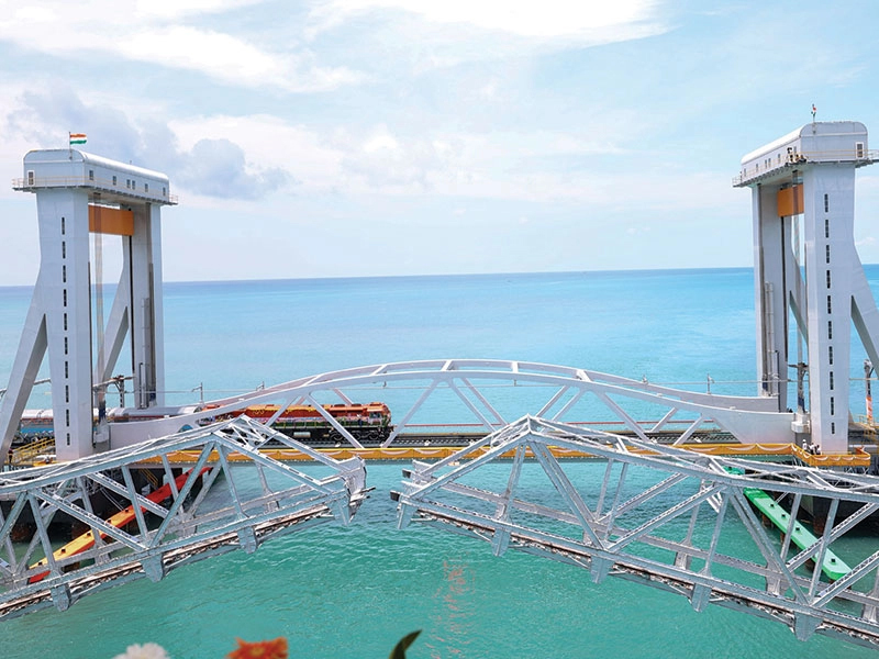
The unique Signature Bridge with its peculiar, slanted steel pylon of around 154m has a span of 251m with 7 number of 36m side spans of composite construction. It was designed in Germany and Italy, its stay cables were supplied from Spain, it was fabricated in China, and supervised by experts from Brazil, Canada and Australia. Overall, eight countries were involved in the project to make it a truly international mega structure.
The very complex geometry of the slanted steel pylon with its three dimensionally varying ‘Namaste’ pose involved high precision fabrication, machining and drilling including trial assemblies of the fabricated segments under strict supervision.
The priceless structure is around 675 m having cable stayed span of 251 m, flanked by approach spans on either side of the main bridge, which has a dual carriage way of 4 lanes each with 1.2 m, central verge for anchoring cables and accommodating a maintenance walkway, crash barrier etc. The total width of the deck is 36 meters. The steel composite deck being integrated with the pylon is supported on spherical bearings of capacity 17100 t, while eight backstays are anchored to a specially designed pendulum bearing, which can take the uplift to the tune of 6380t, which in turn is anchored to a hybrid foundation of caisson and piles.
The unprecedented nature of design of foundations, bearings and the pylon called for ingenious and first time construction engineering and methodology to be evolved whether for hybrid foundations, concrete technology, erection of large capacity and special type of bearings, fabrication, trial assemblies, welding including very long and critical in situ welding of pylon base, and finally segmental erection of three dimensionally varying pylons.
Introduction
The conception of a new 8-lane bridge across river Yamuna 600m downstream of the existing barrage cum bridge at Wazirabad, Delhi, was a culminated decision of the Delhi Government for making a landmark structure and to develop the surrounding area. This necessitated the development of approaches (Western as well as Eastern) on both sides of the conceived Signature Bridge. Western and Eastern approaches as depicted in Figure 1 was a separate contract (depicted as 1) from that of main Signature Bridge contract (depicted as 2).

On the Western side, grade separators comprised of flyovers, loops and ramps were constructed to ensure signal-free traffic movement at the proposed intersection of bridge with Road No.45 and existing intersection at Timarpur, Nehru Vihar and Wazirabad. Road widening, construction of footpath, storm water drains, cycle track and subways were also part of the Western approach into a Tourist Destination. The Eastern approach includes construction of an embankment of about 2.0 km length, river training work, river protection works, widening of existing roads, construction of roads, footpath, cycle track, storm water drain, etc. In addition, a 6-lane flyover was constructed at the Khajuri Khas intersection with rotary at ground level to ensure signal-free movement.
In the last 3 decades, the longest, the tallest, and the biggest iconic bridges have been built in China. However, it is not necessary that a bridge has to be the longest, tallest, etc. to be iconic, but when the identity of the surroundings is known by the bridge and developments start taking place around it, then the bridge attains an iconic status. The Signature Bridge is envisioned to be one such bridge.
Concept
The area under the bridge is envisioned to be developed later as a park and the Yamuna river is to be converted into a lake like dimensions to enable boating and other tourist attractions. The concept and the vison to make the area a tourist destination was entrusted to Architect Ratan J Batliboie and structural designers Slaich Bergermann Partners & Construma by the client DTTDC.
Following innumerable brainstorming sessions, numerous long span lightweight cable stay bridges were created. The challenge was not only to conceive a bridge that would be iconic, but also to have a form following the flow of forces, in harmony with the structural engineering concept, and be symbolic of local culture, tradition, and character.
During the phase of convergence (Figure 2), many options were tested, keeping in mind the fundamental principles enumerated above, before arriving at a solution which was almost twice the height of Delhi’s heritage structure – the Qutub Minar.
There are two more bridges Alamillo and Erasmus of the magnitude of Signature Bridge and with a close resemblance to the peculiar slanted pylons.
Graphics on the bridge structure, particularly on the pylon is perhaps featured for the first time in the world. Once again, the pattern chosen was to symbolise Indian culture and to reflect a modern and progressive India. After having evaluated various options, the peacock’s feather was zeroed in as an appropriate emblem. (Figure 3)

Salient design features
Signature Bridge is an elaborate cantilever spar cable-stayed bridge (Figure 4) comprising of an asymmetrical inclined Namaste shaped Steel Pylon of 154 m height. Total length of the cable stayed bridge from expansion joint to expansion joint is 575 meters, with main cable-stayed span of 251 meters supported by 15 sets of cables on one side and counterbalanced by 8 back stay cables attached at a rocker bearing on axis 23. The bridge steel and concrete composite deck has dual carriageway of 4 lanes (14 m) each with about 1.2 m. central verge, space for anchoring cables, maintenance walkway and crash barrier on either side of the central verge. The outer-to-outer width of the bridge is around 35.20m and the approach spans are about 36 m long. Spherical bearings are provided on all the piers and pendulum bearings are provided for the back stays.
The Steel Pylon of around 154 meters from top of the bearings consists of two legs made up of steel boxes which merge into one upper pylon body zone made up of a load bearing skin stiffened by internal stiffeners and bracings, where the cable supporting the main span and the back stays are anchored. Each of the pylon legs consists of a hollow steel box which would be roughly 50 – 80 meters high. The upper end is the kink diaphragm which is the transition from pylon leg to the pylon body.
It also has a pylon head, made up of beams and columns in steel structure with a glass cladding. Major part of the steel for pylon is of grade S355. In very highly stressed anchorage zones, S460 grade steel is used. Each leg of the Pylon rests on spherical bearings to transmit vertical loads of around 17,000 T.
The deck spans 32 m in transverse direction for 8 lanes of traffic, 4 lanes in each direction. The composite deck consists of two main girders (I-shaped) in longitudinal direction and cross girders at 4.5m spacing along the deck. Spans are of 13.5 m long on the cable supported part, 36 m on the approach spans which are supported over concrete columns. Most part of the deck slab is made up of full depth prefabricated concrete elements of varying thickness from 250 to 350 mm, stitched in-situ over steel girder flanges. In highly stressed areas, near pylon base and backstay anchorage, in-situ concrete up to 700mm thick is used.
The cables are made up of bundles of parallel 15.70mm strands of class 1770 Mpa, protected against corrosion with hot dip galvanization and outer PE-pipes. Depending on the location the number of strands per cable varies from 55 to 123 nos. at the main span and is 127 nos. for each backstay.
Under the axis A and C, the independent foundations are provided up to the depth of 20m below ground level as generally rocky stratum was geo technically determined at that level.
There are 6 open foundations (Figure 5) resting on rocky strata at a depth of about 20 m. The diameter of the main Pylon P19 foundation (2 nos) is 23 m with pier dia. of 5.5 m and that of lateral spans having foundations at P20 & P3 (2 each) is 7 m with pier diameter of 2 m. The remaining 16 numbers are well foundations with the varying diameters of 8 to 9m while back stay foundation P23 has a hybrid foundation, which is a combination of piles and wells with the tapering well dia from 17m to 15.50m.
Realisation of special foundations & substructure
The cable stayed bridge with steel pylon and composite deck has foundations (Figure 5) of the following types:

(i) Six nos. of open foundations resting on rock strata at a depth of about 20 m. The diameter of the main Pylon P19 foundation (2 nos) is 23 m with Pier dia. of 5.5 m and that of lateral spans having foundations P20 & P3 (2 each) is 7 m with Pier dia. of 2 m.
(ii) 16 well foundations for the remaining piers, with dia. ranging from 9/8 m to 17/15.5 m for P23 back stay pier.
The sub soil strata at site is generally homogenous and comprises mainly of two types of layers: dark grey fine sand in the first layer and in the second layer light brown sandy silt up to the rock layer around 20m below the ground level. The rock met is generally weak to moderately strong quartzite.
As the open foundations were to be rested on rock by about 20 m below the ground level, sheet piled cofferdam (Figure 6) was used for excavation by lateral support system (ELS).
Staged excavation analysis accounted for the actual sequence of excavation and brace installation by considering each stage of the excavation as it was constructed, including supports installation and removal. The expected soil and water pressures were applied in the system at each stage. The models incorporated interaction of the soil and structure as the earth pressure vary with displacement.
In the designed arrangement, the sheet piles were expected to rest on rock as such suitable restrain was required to resist the shear generated at the tip of the sheet pile. Anchoring the temporary sheet pile cofferdam wall into the rock was ruled out as anchoring & retrieval of sheet piles would have been herculean task.
In order to develop passive toe resistance, vertical shear pins were designed and installed into predrilled holes in the competent bedrock to provide lateral resistance, thereby avoiding the need to provide another layer of waler and strut at that lowest level of the sheet pile.
For this purpose, a Toe pin consisting of steel pipe of 273.5 mm dia. & 5.9 mm thick. With ISMB200 and concrete grout (embedded about 3m deep in rock) were installed at 1.5 m c/c all around the perimeter in front of sheet piles on excavated face (Figure 6).
All well foundations were required to be done adopting jack down method of sinking for controlling the sinking operation without tilt and shift. In the client’s design, wells were proposed to be supported on concrete block stools for enabling bottom plugging and 100mm dia. anchors to resist the sliding. Placement of stool blocks beneath the sloping well kerb under water was not only impractical but also was high risk prone. The cleaning of the base beneath the kerb by divers before placement of stools was posing the possibility of well sinking suddenly jeopardising the lives of divers working under water as such 230mm dia. micro-piles (Figure 7) were schemed, designed and adopted as the final solution for facilitating both plugging and resistance to sliding.

Pylon & Back stay anchor foundations
The signature bridge P19 pylon foundation has two massive independent open foundations 19 to support peculiar pylon legs (Figure 8) that are resting on rock at around 20 m below the ground level. The foundations are 23 m diameter having an edge thickness of 2.5 m and tapering to pier diameter of 5.5 m in a height of 2 m, thus making the total depth of the foundation to 4.5 m.
For each foundation 28 m square × 18 m deep sheet pile cofferdam (Figure 9) was constructed by driving AU 25 sheet piles by vibro-hammer. As the excavation progressed in stages through sandy and clayey strata, till the rock level at around 19 m depth was reached, the cofferdam was stabilised by struts and walers at four designed levels.

Since the sheet piles could not get sufficient embedment in to the rock, the same were pinned by Toe pins made up of 230 mm diameter pipes having ISMB 200 sections inserted and pressure grouted.
The back stay P23 foundation is a very critical foundation, as the same has to neutralize uplift of 6000 t under critical load combination (Figure 10). Originally, the foundation was designed as 2 independent wells with maximum diameter of 17.5 m each connected by a common well cap of thickness 4.5 m. The wells were designed on the basis of single bore holes at the CGs of the wells and was terminated at around half meter above rock line, assuming horizontal rock line.
As in the river Yamuna, there were instances of sloping rock; geotechnical investigations were carried out around the periphery of both the wells, before taking up the actual construction of foundation. To the surprise of all rocky strata was varying drastically within the diameter of wells. It was as high as 9 m from one edge to the deepest point within the well diameter. This warranted a change in the design.

In the revised design, 16 numbers of 1.2 m diameter was provided in each well through the steining and anchoring into rock by 6 m. Wells were sunk by Jack down method of sinking and as the steining was built up with 1.3 m diameter voids left in the steining, so that 1.2 m diameter piles could be done later through these voids. Bored cast in-situ piles were done using specially imported RCD rigs. The sequence of construction is depicted in the Figure 11.
Bearings & their configurations within cable stay bridge system
There are twenty free spherical bearings, two large fixed bearings under pylon legs, two numbers of longitudinally guided spherical bearings (Figure12) at the location of expansion joints to enable reversible movement of 270mm and rocker bearings under backstay anchor foundation which can transfer the tensile force of 6380 t within the main cable stay bridge system.
Typically, the bearings are placed to support longitudinal plate girders on A & B axis as shown in the Figure 13. The bearings are typically pre-set for transverse movement, longitudinal movement due to elastic shortening of the girders and rotational movement due to pre-cambering in the transverse direction as depicted in the same figure.

The special attention was warranted to detail the fixed bearings under the pylon legs at P19 foundation location and rocker bearings where 8 numbers of back stay cables are anchored to P23 foundation.
Installation of bearings at P19
The fixed spherical bearings (Figure14) are provided under each pylon legs with the maximum vertical capacity of 17100 t having transverse & longitudinal horizontal capacities of 2710 t and 1970 t respectively. The bearing on A axis at Pylon location is fixed while on B axis during construction stage bearing was to accommodate the movement of -10mm to +50mm which would be fixed during service stage.
The bearings are located at the intersection of pylon cross girder and longitudinal girders on A & B axis and connected rigidly to a very heavy (nearly 400 t) pylon base (Figure 14). The bearings manufactured and load tested at Germany warranted special erection schemes & high capacity cranes due to its huge volume & weight.

After having installed the massive bearings using 300t capacity Gotwal crane, the pylon base units weighing more than 400 t were placed in position by 1250 t capacity Sarene crane.
Rocker bearings at P23
The P23 foundation in the signature bridge is designed to carry the upward tensile load of around 6380 t transmitted through back stay cables from the pylon for a particular load combination. This uplift load has to be resisted by the dead load of two wells filled with high density concrete that are finally anchored to stratum by 32 nos. of 1.2m dia. piles. The 4 pairs of the rocker bearings (Figure15) acts as a tensile link between pier and well cap which houses 320 nos. of 36 dia. post tensioned bars.
Well cap of Length 42.320,breadth 16.320,depth 4.50m was cast with great care as bed level of well cap was approximately 10m deep from the surrounding level and 2850 cum of concrete embedded with 500 t steel was to be poured in one go.
Looking at the criticality of well cap (Figure 16) being a link between substructure (pier embedded with 320 numbers of 36 diameter PT bars & pendulum bearings) carrying tension & compression and foundation giving rise to counter weight to resist tension under particular combination of actions, the well cap was specified to be constructed at one go without any construction joint. Further to compound the matter complex the mass concreting in highly reinforced congested environment was to be carried out in the ambience temperature of around 100 Celsius. This led to another challenge of controlling the induced thermal stress owing to hugeness of the foundation and heat of hydration owing to high cement content required to get the requisite grade of concrete at required workability within the stipulated technical specification. Once the concrete of backstay pier achieved the desired strength, lower part of the rocker bearing (4 Nos.) were placed through the DSI bars in their correct global position/coordinates.

After erection of girders up to CG 3022-6 (Figure 17), upper part of the rocker bearing was placed in 6 parts one by one on the temporary supports. After erecting the same in position, the pendulum plate of the lower part of bearing is rotated to get connected with the upper part of the bearing by insertion of pin as shown in the figure18 as per the instructions of bearings supplier.

After installing all the pins in the bearing, entire assembly was lifted to the desired design elevation with the help of hydraulic jacks on temporary trestles. The 100mm thick motor bed with Shrinkage resistant mortar below the lower part of the bearing as well as grouting of gap between block out tubes and DSI bar were required to be done. The deck position was adjusted to match pre-set adjacent elements by using jacks: longitudinal shift +23mm towards P26 transversal shift +20mm towards axis A (upstream). The incremental stressing (1 bar increment) of PT bars was done one at a time to the prescribed sequence and 72 t prestressing force was induced to backstay pier per bar.
The challenge was to coordinate between the Chinese fabricator and German bearing manufacturer (Figure 19). The backstay anchorage assembly was fabricated at China. Pendulum bearings were manufactured in Germany. Therefore, part of the bearings especially the rings housing the pins were sent to China from Germany to be fabricated into the top plate of anchorage assembly involving customs clearance at two countries.

Construction engineering
In an item rate contract like Signature bridge, starting from the final design, the bridge has to be constructed based on a system of detailed construction design called Construction Engineering (CE), which is the complex activity aimed to define and design the entire construction process as well as the construction of structures and equipment needed to build the bridge. The importance of Construction Engineering increases proportionally with the size and complexity of bridge. While the Final Design assumes that the bridge is a completed single structure, Construction Engineering must take into account the evolution of bridge construction and the numerous intermediate partial structures that arise, grow and evolve during construction.
The number of drawings required by CE is much larger than the number of drawings that define the final structure, and the designing work for large structures, is also greater. Signature Bridge, because of its large size and the unusual shape of its tower, required a challenging CE and many interesting problems, illustrated below, also had to be solved.
Assessment of fabrication complexity
Construction of super structure involved fabrication and erection of about 14500 Mt of structural steel for permanent deck and pylon and around 17000 Mt for temporary enabling structures. The distinct characteristic of Signature Bridge is its Pylon integrated with the composite deck and hinged at pier top level. The pylon with its harp shaped body, leaning backwards, would be the most unstable structure during construction stage. During construction engineering phase a detailed step by step erection methodology was developed to understand the behaviours of the structure at various stages of erection. Analysis of structure under various erection loads including temporary structure was performed to understand probable strengthening required to the structure during fabrication & erection stage.
Pylon is a 3-dimensional complex structure having inclination in all planes. It is made up of irregular panels welded out of varying steel plates of different grades. To thoroughly understand the complexities of the structure, dimensional weights of the elements to be fabricated, transported and erected, a true to scale digital model (Figure 20) of the bridge was prepared in Tekla (steel detailing software). It incorporates a Building Information Modeling (BIM), enhancing efficiency, accuracy and substantial reduction in wastage of material through proper detailing.

Deck was comparatively easier, but the same was also modelled to understand the integrated parts with pylon, such as tie beam, rocker bearing and anchorages. As an outcome of the digital model it was understood that, pylon was a complex structure consisting of main panels made up of highly irregular stiffened and plated box sections of varying sizes. As per original design, maximum panel sizes were about 6.5 x 6.5 x 15 m and weighing from 60 MT to 560 MT.
A feasibility study (Figure 21) was done, by means of route survey to understand logistics challenges involved in transportation. It was realized that it was almost impossible to transport these oversized and heavyweight segments from fabrication shop to site over Indian road and bridges. To overcome the hurdle of restrictions on transportation, the pylon was divided into sub-panels of transportable size (Figure 22) by introducing additional splices. Except for some welded joints at site, all additional splices were introduced as bolted connection.
It was proposed to fabricate these segments in an established fabrication workshop and then transported over road to site, where they would be reassembled before erection.

Panelling, preassembly, machining & trial assembly
With most logistical issues resolved on the drawing board, fabrication works started with new set of challenges. Pylon & Deck fabrications were the most technically challenging part of the job with required high level of accuracy with stringent specifications due to the uniqueness of the structure.
Some major challenges in fabrication:
- Use of plate having thickness ranging from 2.5 to 250mm including Z quality steel (plates above 80mm and special grades not readily available in India)
- Adoption of appropriate welding sequence to avoid deformation
- Preheating up to temperatures in excess of 600 degree for thicker plates
- Stress relieving arrangements due to heavy welding
- High precession and tolerance requirement for bolt holes & end milling
- Drilling almost 8,50,000 holes for HSFG bolts ranging from 12 to 36 mm in plates up to 120mm thick.
- Availability of skilled manpower
- Requirement of special lifting equipment during fabrication & trial assembly
- Availability of well-equipped fabrication facility, etc.
- Machining facility to carry out 36m long surface at one go.
Two methods for drilling of holes were specially devised. Pre-drill holes on the web plate of the connection during panel fabrication and post-drilling method was applied for other holes which were marked and drilled with templates after fit-up, welding, rectification and milling of segments.
All the compression joints were designed to transfer load through bearing contact surfaces along with splice connection. To achieve appropriate bearing surfaces, all the contact surfaces in compression like main girder edges, pylon horizontal joints would be machined to have a surface planes not more than 0.3mm per meter. Longest machined surface was as long as 32m for pylon kink.
Some typical steps followed in the fabrication process:
- Technical groundwork – preparing fabrication drawings, workout requirement of material, equipment and support arrangements.
- Procuring and testing of Raw material
- Cutting of material as per approved fabrication drawings.
- Panel welding and NDT testing
- Fit up of a segment and NDT testing
- Initial survey and dimensional check for fit-up segment. Conduct rectifications if required
- Machining end surface of the segment in contact with other surface at splice, which transfers load through bearings.
- Match drilling
- Trial assembly, match drilling and final survey
- Blasting and painting.
Trail assembly was performed in line with the sequence of erection at the bridge site. It was ensured that trial assembly jig had enough rigidity to avoid subsidence. Trial assembly for deck was carried out for minimum 5 segments.

The pylon included four parts (Figure 24): steel leg segments, main body, pylon head segments. Steel leg was divided into 11 large segments L0 to L10, among which L1 to L6 were made up of two small blocks each. Main pylon body was divided into 5 large segments MB1 to MB5, each of which was made up of two small blocks. Front cable pylon was divided into 5 large segments F0-1B to F4-1B while rear cable pylon was divided into 5 large segments B0-1B toB4-1B.
The special attention regarding the following key points was warranted to decide the fabrication, trial assembly and geometric control procedures:
- The accurate geometric dimension of pylon structure with edge considering their complex configuration with heavy welding in volume and the control in welding shrinkage and in the structure deformation during and after welding.
- The quality of thick-plate welding.
- The requirement on the accuracy of bearing contact in end face considering their huge vertical compression of the pylon tower and its shaped alignment.
- The trial assembly was to be carried out to ensure the geometrical alignment. The jig platform should be set in a rigid and accurate way that its features would not affect the accuracy in the trial assembly and final adjustment of sectional segments, consisting of 3D configuration of leg, main body with front and rear cable stay structures.
- Keep the temperature changing in an acceptable range to constantly maintain the precision in fabrication of the pylon.
- Due to the huge size of the pylon segment with heavy weight, to avoid any deformation or prevent any damage done to the machined contact surface of the segment and the structure itself, during transportation.
- Geometrical alignment of pylon segment together with the site welding control.
- Control in painting quality.
- Pylon kink segment F01-B, a transition segment to connect steel leg and main body, is a complicated structure with machining of joint surface to be precisely controlled during fabrication.
Pylon base segment (Figure 25) was fitted up and welded from bottom to top, symmetrically from middle toward outside on the jig. Ordinary fit-up method (fabricate as per the as-built drawings) and reversed fit-up method (fabricate upside down) was adopted for the fabrication of pylon base segment.
The structural configuration of the stiffeners and the varying thickness of the plates from 80mm to 250 mm was so much painstaking for fabrication that could only have been executed to the final precision by Asian fabricators without much fuss.
For the pylon leg and main body components, the segment fit-up and shop assembly was carried out with 3 batches (Figure 26). The last section from the previous preassembly was included in the next preassembly as a starting guide reference to guarantee continuous linear shape of adjacent segments.

For the steel leg components, after completion of paneling fabrication, a longitudinal assembly line on the ground as reference datum was set and marked. Inside panel was taken as base plane, and its axis was matched with the reference datum marked on the ground. Then all the related weld panels and outside panels were continuously matched, welded and preassembled to complete all the leg segments. Assembly for both left and right leg segments were carried out simultaneously at the same time. After all segments in the batch for the preassembly were accepted, were taken off jig and sent for machining appropriate identification marking.
The kink segment (Figure27) was the most important part in fabrication. After having finished the fabrication of panel units and truss structure of the segments, the fit up of the segment was done on the jig as per the designed mark on the ground. The outside plate was to be designed as the base surface and the fabrication was carried out by the side way. The fit up, welding and shop assembly of the kink was done at the same time. After acceptance of the assembly, the temporary splicing plates was fit up and the kink segment was marked, taken off from jig and sent to machining area.

Steel leg segments of L101-B, L91-B, L81-B, L71-B was included in the second batch preassembly (Fit up and welding of the connection parts of leg and main body). L6 1-B and FO 1-B segments which included in the first batch, had to be included in the second batch as the starting guide reference to guarantee continuous linear shape of leg segments and main body. Fit-up, welding and preassembly procedures for pylon main body segment is almost the same with those for the transition segment.
Preassembly jig was specially designed according to the profile of the pylon and had to be capable of adjustments in three directions: movable in longitudinal direction when compression is put on the segments along the axial direction, movable up and down and in the transverse direction when splicing, alignment and adjusting the axis. Preassembly was performed when the ambient temperature was stable and temperature change of components was not very high under the constant monitoring of surface temperature within the control environment.
Overall, there were 32 surfaces in the pylon at 16 locations including bottom and top face where machining requirements were there. The maximum length of the milling to be done at one go at the kink location was around 32m. One of the conditions for subcontracting fabrication was that the contractor had to have milling and drilling equipment capable of doing machining for 36m length at a go as such subcontractor procured the equipment from Spain specially for Signature bridge project.
Steel pylon segments were transported to the machining workshop to equalize the temperature 12 hrs before commencement of machining. temporary diaphragm were needed to be installed on the opening of the and before machining in order to avoid vibration of the head plates caused by machining.
The trial assembly was carried to check out precise matching with segments not less than 4 segments. The last segment from the previous trial reassembly shall be included in the next trial assembly as a starting guide reference to guarantee continuous linear shape of adjacent segments. The purpose was to inspect the surface contact rate of head plates between segment after machining, the bolt hole through rate, deviation of axis among segments and check the feasibility of machining procedures and preciseness of machining.
The steel leg segments, transition segments connecting legs to main body warranted dedicated assembling jig.
Surveying and measuring of geometric dimension and alignment of pylon segments were performed. The deviation of alignment collected was compensated during the machining of the next segment.
Engineering for erection
Cable stayed bridges are usually symmetrical in nature and traditionally built by cantilever construction. An unsymmetrical cable stayed bridge like Signature Bridge with an inclined pylon, supported on bearings, is a highly unstable structure during erection. This demanded for an innovative method of erection with a well-coordinated and calculated step by step erection procedure.
The pylon is composed of two legs, box girders, inclined backwards and inwards and connected at a level of +63 m by a main body, that is a vertical shaft with variable cross section, which hosts the top anchorages for the stay cables. The legs have a rectangular box girder with a constant width of 2.50 m and height varying from 7.20 to 9.60 m. The Main Body, still a box girder, has a maximum width at its base of 20m and a minimum width at the top of 13 m. The two legs are hinged at the base so they would be unstable during erection, unless some sort of device was provided. The pylon was divided into segments with weights varying from 40 to 250 t. The joints between segments were flanged bolted joints with machined flanges. The connection between the Main Body and Legs is created using flanged joints, machined at the workshop, with a total length of 32m.
The main design problems to be solved in order to erect the pylon were essentially:
- How to stabilize an inclined structure hinged at its base during construction;
- How to recover structure deformation during erection;
- How to install large, heavy box girder segments that had to be placed, one above the other, in a position with double inclination;
- How to manage the temperature effect, together with the tight tolerance of a bolted structure.

Based on the methodology proposed for erection and construction stage analysis, temporary prop arrangement (Figure 30) is designed to support the pylon. These props are not only designed to support the structure, but also to maintain and ensure correct geometry, with the help of suitable jacking arrangement. Special tie down arrangement was installed at the base of the pylon to stabilize the initial phase of pylon erection.

Deck girders were supported over temporary trestle and erected using a Goliath gantry running over the same trestles along the bridge. Pre-cast deck panels are erected over girders using same Goliath gantry for deck erection (Figure31) towards the river side while girders and precast panels were erected on land side with crane.
The majority of the deck concrete was in precast panels (Figure32) stitched by cast in situ concrete on top of the main girders and cross beams, except in the highly compressed P19 and P23 locations (Pylon & backstay anchor) where slab thickness was varying from 250mm up to 700mm with 7 layers of reinforcement.

Overall, there were 528 precast panels of 4 types, generally having plan dimension of 7.5m X 4.0m with 250mm thickness. These were cast at casting yard (Figure33) equipped with 10 casting machines & a bed gantry of capacity to handle precast panels of around 20 t.

A detailed stage-by-stage analysis (Figure34) was done to determine stress distributions in the structure for all intermediate stages and to perform structural adequacy checks for erection stage. Sufficient strengthening of permanent structure was done wherever required.
Sufficient strengthening of ground for movement of heavy equipment’s is also provided. Specially designed tilting and lifting frame is designed and developed suitable for erection of segments with varying shapes and sizes to optimise permanent works design and minimise additional temporary works required during the construction stage.

The correct positioning, with double inclination, of pylon segments was achieved by a specially designed turn table (Figure 35):
- After assembling the Segments horizontally, they were shifted to a special jig made of three layers.
- Then the bottom frame was tilted longitudinally in order to get the proper longitudinal inclination.
- The top frame was then tilted transversally in order to achieve the proper transversal inclination before being propped;
- Lifting lugs were installed on the segments using the flange joint holes.
- Slings of proportionate length were finally installed.
- The position of the lifting lugs and the length of the slings were designed so that upon lifting the lifting hook would be positioned on a vertical axis passing through the Centre of Gravity of segment.
A careful monitoring of the geometry throughout construction would be required to ensure that the structure behaved as predicted and the target geometry was met. Since many of the quantities involved in the construction are only approximate values (exact elements dimensions and weight) or can be measured with a given tolerance (stay cable lengths and forces) and environmental conditions change during construction, and the calculation model itself is only an approximation of the real structure, a continuous monitoring of structural deformation during the construction is of fundamental importance. For this reason, structural geometry was checked by DMA at every element installation and a daily survey procedure started at the beginning of stay cable stressing.
Temperature changes, mainly during the day due to direct sunlight, modified the real/actual geometry of the structure, continuously changing the position of working points making it almost impossible to install the pipe elements in their theoretical position. Structural movement over time, detecting the hours in which the joint distance was larger than theoretical was monitored, and these hours for installing the elements were set, fixing them only at one end and leaving the other sliding. Then, during the hours in which that distance tended to close, the other end bolts were installed and tightened only at the time in which the theoretical geometry was achieved.
Survey data were collected and examined for all the relevant erection stages, based on survey points which were marked during trial assembly. Initially especially after pylon legs merged in to pylon body daily survey of a new series of pylon and deck points started, with the aim of identifying also the movements independent from installation of new elements and cable stressing and separate environmental actions effects (temperature, sun irradiation, wind) from construction effects. A sample of results from a 3 day survey (every 2 hours) is depicted in the Figure 36.
While monitoring the effects of construction loadings, element loadings and cable stressing on deformation of pylon & decks, the following correction factors of the environmental effects had to be applied. The Pylon position changed rapidly during the day, with movements around 20mm in longitudinal and vertical direction and up to 40mm in transverse direction. Displacements followed the same trend during the day. Apart from survey tolerances (total station and operator), movements due to temperature, sun exposure, wind, vibrations, could also influence final acquired points coordinates. Survey data collected at different time during the day (also one or two hours) could also lead to apparent inconsistencies.
Stay cable system consisted of 19 pairs of cables with varying number of strands minimum being 55 to maximum of 127 of 15.70 mm dia. with GUTS of 1770Mpa. The reference lengths of the cables (deck bearing plate to pylon bearing plate distance) varied from 85m to 285m.
The passive anchors being at deck location, the active anchors from where stressing was to be done was at the location of pylon main body. Stay cable strand preparation consisted of pulling out the strands from coil drum, laying on the bench, uncoating, cutting & marking for identification. After having installed anchorage boxes with bearing plates at pylon top & deck levels, the welded HDPE ducts and form tubes were hoisted on the threaded initial strands.

Strands in the cables were tensioned (Figure 37) using iso elongation method. This method utilises mono strand jack attached with a load cell, hydraulic pump, dynamometer for calibration of pump-jack system. For each stressing phase, the strands was first stressed up to the 80% of the stressing force.
Each strand was stressed up to the elongation needed considering the elastic elongation of the steel strands and movement of pylon and deck during the stressing operations.
A topografic survey of the bridge during each stressing phase was provided. After reaching the 80% of the stressing force in each phase, new elongation to be applied to the strands had to be provided considering the actual load registered and the data collected from the topographic survey. After accounting for the new elongation provided all the strands was stressed up to 100% of the stressing force.
As the pylon grew in stature, the access (Figure 38) to the working locations of HSFG bolting, pre-tensioning, shifting of jacks and other accessories had to be enabled by specially designed platforms, cage ladders and passenger hoist equipped tower crane. The connection between growing pylon and tower crane was engineered in such a way that there is no unscheduled horizontal force either on pylon or on tower crane.
The grid method was used to create peacock feather on the pylon. In this method drawing process starts once the final coating of base colour i.e; green Beige has been applied on the pylon segments inside a specially designed shed (Figure 39). Grid is marked 1000 mm apart all over the surface. In areas comprising intricate design smaller grid is marked on the existing grid to increase the accuracy. Drawing is marked grid by grid on the whole face of the segment.

Proper measurement is kept for reference of adjoining parts of next segment up to a millimetre’s perfection. Once the drawing is marked the negative areas are masked (with 3M masking tape) before painting to avoid over-painting or leakage and dripping of paint. After completion of open space painting process and once paint is thoroughly dried, masking tapes are removed and the bi-colour graphics come out. A transparent protective layer is applied if paint specification recommends so.
At the time of writing this paper, 95% (Figure 40) of the project was completed and the balance comprising the erection of M5 level main body of pylon, glass façade of the pylon head and 4 pairs of cable installation & tensioning was expected to be completed by September 2018.
Mega project aspects
This iconic bridge had to overcome the challenges true to its stature from inception through conception to commissioning. The structure was finally inaugurated on 4th November 2019 with a grand fanfare, emotional speeches by the state heads, an exciting laser show and perhaps an unprecedented gathering of public on the bridge deck. The gathering was so huge on the completed deck (Fig.41) that the designer of the bridge Prof Mike Schlaich who was on the deck during the inauguration remarked to the author: “There is no need for load testing of the bridge as perhaps the bridge is already subjected to in excess of the loading designed for!”

Huge sizes, three dimensionally varying inclined tall structure and enormous weights to be lifted warranted a detailed and holistic study of construction methods, rigging plans and fabrication of structure to suit construction methods along with constantly checking the structural behaviour and deformations. As the segmental construction of three dimensionally varying pylons was being attempted first time and being not time tested, there were many unforeseen issues which could be overcome by only scientific Construction Engineering.
While the completed structure (Fig.42) is there physically standing tall to be admired in the years to come and to get many accolades for its design, the construction engineering which is very complex for a structure like this including, full scale digital model (Tekla), plants, enabling structures, milling machine capable of 36 m long surface at once, a 1250t capacity crane, and the specially designed turntable to enable rigging of three dimensionally varying pylon segments, will remain unsung heroes of a once-in-a-lifetime project.
The nature of the contract necessitated domain experts from 10 countries from diverse backgrounds and cultures and with savvy and innovative managerial skills in terms of design co-ordination and contract administration, qualities which perhaps are not taught in the best of management schools.
Acknowledgements
- Owner: DTTDC - Delhi Tourism and Transportation Development Corporation
- Designer for Owner: SBP - Berlin with Construma - Delhi
- Contractor: Gammon - Construtora Cidade, Brazil - Tensacciai, Italy : Lead as JV attorney - V N Heggade
- Consultant for Contractor and Construction Engineering: DMA - Studio de Miranda Associati - Milan - Italy
- V N Heggade, My tryst with Namaste Signature Bridge, Padma Vibhushan Prof Jai Krishna memorial lecture, 36th Civil Engineering convention by IEI, 23/10/2021.
- V N Heggade, My tryst with Namaste Signature Bridge at Delhi, O P Jain memorial award receiving lecture, IIT Roorkee, 10th March 2022.