
Location
The bridge lies in the state of Assam, but this location is usually referred to as upper Assam as it is far away from Guwahati and bordering China. The nearest airport is Dibrugarh. Then there is a drive of 65km into the north, passing through an important town Tinsukiya, on the way.
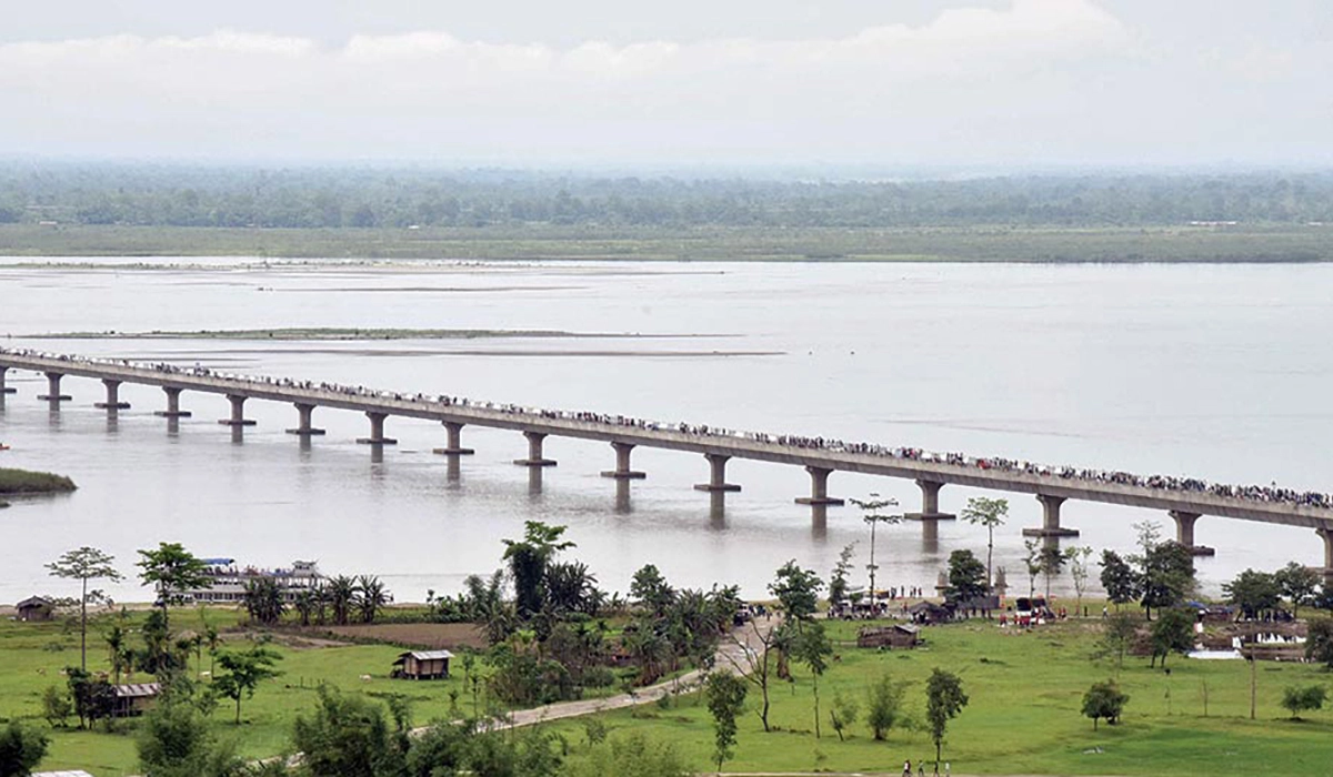
Dhola is on the southern side of the river while Sadiya is on the north. The bridge crosses River Lohit. Here again some explanation is needed. River Lohit flows in from China. There are two other rivers (river systems) that flow in similarly. They are the Debang river system which is a network of river channels and the Siang river system. These three join together downstream of the present Dhola-Sadiya location and is thereafter called River Brahmaputra.

The perennial river proper is only 4000m wide, but the bridge is 9150m long. When the river is in spate, it flows over a wide area. The 9.15km stretch tries to cover this but there could be breaches during flooding. The structure over the flood plains is called viaducts. Viaduct on the Dhola side is 2600m long and on the Sadiya side it is 2550m. This river provides a difficult barrier between South and North Assam. Several projects have been planned in Northern Assam, which is rich in hydro-electric potential. In fact, many hydro-electric projects are pending as the important crossing of the river Lohit was not completed. Now, opening of this bridge has thrown open immense possibilities. This will open a route from the northern Assam to Arunachal Pradhesh as well – an all-important connection that would propel the area to intense development.

Difficult Conditions
The location is fraught with difficulties. One is high seismicity. The country is categorized into four seismic zones based on expected intensity of earthquake. This location falls under zone 5 which has the maximum intensity. Another condition is the high wind speeds. Though this is not a coastal zone, the wind velocities are high. Design wind speed is given as 50m/s. Coupled with these, the current velocities in the river are high. Design current velocity is given as 3m/s. Design of a structure in such conditions is difficult. But the subsoil consists of fine sand which is comparatively a favourable condition.

The Structure
The bridge piers are founded on piles. There are four piles supporting each pier. For the sake of design of the foundation, the bridge is divided into two parts: proper river portion and flood plains. In the river portion there will be perennial flow of water and also it is deeper. Piles in this portion are subjected to higher forces than those in the flood plains. The flood plains will be dry during non-flood period. Scour of the bed in the river portion is deeper and current forces on piles will be higher. Besides, horizontal forces from seismic activity, braking of vehicles and temperature variations will induce heavier bending moments on piles.

Basic span of the superstructure is 50m. Totally there are 183 spans with 101 over the flood plains and 82 in the river portion. What is important is that apart from the bridge proper, the high earthen embankments approaching from both ends constitute important components. These approaches together measure 28515m. There are some minor bridges also located in the approach embankments. Width of the bridge is 13.2m. This includes a motor carriageway of 10.5m with 0.9m footpaths on either side. For the safety of vehicles there are two crash barriers on either side.
Foundation
Bored cast-in-situ piles have been employed for the foundation. Since forces on the river portion are higher, piles in that reach are of 1700mm diameter while that in the flood plains are of 1500mm. Number of such piles under a pier has been kept the same – four. Piles are to resist vertical and horizontal loads coming on them. They transfer vertical loads on to the subsoil by friction between soil and pile and also resistance from the tip by the soil. Piles are 40m in length. Total number of piles (1700mm) in the river portion is 324 and that in the flood plain (1500mm) is 412. These piles are connected at the top with pile caps. The cap in the river portion is 7.3m square and 2.55m thick. Pile cap in the flood plains is 6.4x6.4x2.25m. Bottom of the pile cap is kept sufficiently above low water level to facilitate casting the caps. Vertical load on piles in the river portion is 520 tonnes. Piles were load tested for 1300 tonnes to satisfy their performance. Concrete used for piles had strength of 40MPa. Steel reinforcements for the pile had strength of 500MPa. Piers transferring the load from the super structure are located at the centre on top of the pile cap.

Superstructure
The superstructure is of segmental box type. The box is externally post tensioned with high tensile strands. In the olden days, bridges used to be constructed cast-in-situ. The implication is that casting of the piles, pile cap, and pier cap in a serial manner is done first. Pedestals and superstructure will be cast next. All operations are to be done one by one in a serial manner. This will take a long time. The present method is to pre-cast the superstructure so that this can be placed in position once construction reaches the bearing level. One problem faced here was that a full length box cannot be transported from the casting yard, lifted and placed in position. So, the box is cut into pieces. This is called segmental construction. There are special design features to be looked into in a segmental bridge. At the interface of the segments, shear keys are to be provided. For the sake of handling, the weight of the segments has to be limited to a minimum. They are to be longitudinally post tensioned. In Dhola – Sadiya Bridge, the segments are externally post tensioned. This will avoid cables passing through the inside of the web of the box and will reduce its thickness and thus the weight of the segment. Besides the deck of the box is transversely post tensioned to reduce its thickness and weight. In externally post tensioned segmental boxes, cables could be seen from the outside. The post tensioned concrete has strength of 50MPa while the high tensile steel strands have a tensile strength of 1860MPa. For a span of 50m, the number of segments used is 15. The superstructure of the bridge rests on elastomeric bearings that will accommodate the rotation and translation movements of the girder. Design of the structure is done as per IRC codes 112 and 6.

Abutments
Abutment is the interface of the bridge with the approach embankment. Abutment becomes complex based on its height. On one side of the abutment, soil will be retained. The structure resists the lateral earth pressure of the embankment without passing on any horizontal load on to the piles adjacent to it. On the Dhola side, the height of the embankment is 10m. This was quite high. A box had to be designed to cater to the earth pressure. On the Sadiya side, the height of retention was 6.5m and so a cantilever retaining wall was designed.

Implications of high seismicity
As mentioned earlier, location of the bridge is in seismic zone 5. This is the zone of highest seismicity in the country. Seismic force acts horizontally and vertically. This is in the form of an acceleration imparted to the structure. Force is the product of mass and acceleration. The acceleration is expressed as a fraction of the acceleration due to gravity. An important thing is that this force could act in any direction and so the structure should be designed for that eventuality. A bridge is a top heavy structure. Considerable mass is centred at the top. Seismic force acts through the centre of gravity of this mass. A horizontal force that acts at that level will induce heavy bending moments in the pier and more so in the piles. Piles and piers have been designed for this force. But this force has to be transferred successively from the superstructure down to the foundation. The final resistance of the seismic forces comes from the soil below. But at every connection, there should be effective load transfer. This is more so at the bearings. The superstructure simply rests on the bearings. It should be prevented from moving sideways or falling out of the pier. This is done by seismic arresters. These arresters resist the seismic loads and transfer them to the pier. They resist transverse and longitudinal seismic forces. Vertical reinforcements are used for transverse forces and stress bars have been utilized for longitudinal forces. Vertical seismic force could either be downwards or upwards. Downward force will be transferred to the soil. Gravity will act against upward forces.

Technique of reinforcing and post tensioning
Concrete is strong in compression but weak in tension. So, in reinforced concrete, as the term indicates, wherever tension is expected steel bars are provided to resist it. Plain concrete is not used in structural members. Judicial use of steel with concrete is the norm for good structural design. What is used in Reinforced concrete is high yield strength deformed bars. They are Thermo-mechanically treated and has a yield strength of 500MPa. In this bridge, piles, pile caps, pier along with its cap and pedestals are made of reinforced concrete.

But concrete superstructure is post tensioned. The principle of post tensioning is different from that of reinforcing. As mentioned earlier, concrete is weak in tension. So, wherever, tension is expected, a pre-compression is introduced. The tension that will occur in the structure will be nullified by the pre-compression. Net stress will be only slight compression. There will be a huge amount of computational effort going into the design of a post tensioned girder, more so, if it is a segmental one. The pre-compression is introduced by means of high tensile strands. These strands are passed through ducts. In an externally post tensioned girder, these ducts are connected to the girder by means of deviator blocks and end blocks. The strands are tensed by post tensioning jacks and anchored to the end blocks. This will induce compression in concrete.

Bearings are made up of elastomers with steel plates embedded in the pads. Steel plates add stiffness to the flexible elastomers.
Construction
Foundation
First construction operation is piling. Of course, simultaneously, the casting yard will be busy with casting of segments. An important aspect of construction is design. Without design, a structure cannot be constructed. So, designs are to be completed first. For the sake of piling, test piles are to be installed and load tested. Then only, regular piling could start. Hydraulic rotary piling rigs were mobilized for this bridge. Batching plant has to be set up for weigh batching of concrete. In fact, the site will become a small self-contained township with men, material and equipment. But when the piling proceeds into waters, suitable arrangements had to be made. Since the waters were wide and deep, it was decided to fill up part by part, do the piling for a small reach and remove the filling thereafter. There was always the impending danger of flash floods. Calculated risks were taken for the successful completion of the project. Once the piling rig moves out into filled up embankments there was no turning back. Filling up of river portions were done by means of excavators.

Superstructure
Long line casting was adopted for the pre-casting of segments. The casting yard was like a gigantic factory. For a bridge of this magnitude, we had to contend with only one casting yard at the Dhola side. It was difficult to set up one at the Sadiya side. To cater for the amount of piers to be cast, quite a number of moulds were fabricated. This was important for uninterrupted work. Moulds for the segments were another priority. Electric Overhead cranes spanning the casting yard were a necessity for moving the segments inside the casting yard. Transverse stressing equipment and strands with flat ducts were required before moving the segments. Mobile cranes were utilized for stacking of the segments. Initial launching of the segments in the flood plains was done by a method called ground supported erection. The launching gantry was not ready at that time. This method was slow. In the river portion, over perennial waters, segments were launched by the launching gantry. Segments were put on trailers and moved on the erected portion of the bridge to the back reach of the launching girder. Segments would be erected in position after post tensioning. Since the bridge was massive the requirements on equipment was also massive.

Flash floods
This was an added risk. This could be catastrophic. We were not used to this when we started work. But information was gathered about the mechanism of such floods. It so happens that in the upper reaches of the river in the mountains, the bed is composed of boulders. These boulders are carried by swift currents and deposited when the current slows down. There is also the possibility that the boulders get stuck on the way. When more boulders get stuck up, it will act like a dam. This will result in water heading up on the upstream of this dam. At a certain point of time, when the head of water increases, the dam breaks and the boulders and water comes down as an avalanche. Once this mechanism was understood we had look out posts in the upstream reaches. When the heading up and subsequent avalanche is imminent, warning in passed on to the downstream site by the look- out posts. People will then get themselves and the equipment out of the way.

Massive requirement
Magnitude of the project was simply huge. Planning from the beginning had to be to meet the massive demand. A sizeable period would be lost due to floods. The planning has to take into account the reduced time available.
Just imagine that a total of 736 piles will have to be installed. This requires infrastructure of a massive scale. Three batching plants and 12 transit mixers were operated to keep pace with the piling. Three hydraulic rotary piling rigs were mobilized. Cranes were required for lifting and placing reinforcement cages and liners. Since there were 182 piers, shuttering for the pile cap was also massive. The pier had a special shape. Moulds for these were a colossal requirement.
Casting yard was another massive entity. Total number of segments for the whole bridge came to 2745. Casting such a large number required a large number of moulds. One salient feature was that practically everything has to come from far-away places.

Floods were very much damaging. On one occasion, we were able to just scramble out of the way a piling rig. But a couple of cranes were lost in the floods. We spend quite a bit of time of salvage them, but to no avail.
During one flood, which was destructive, the approach embankment was cut. The site was cut off from the rest of the world. The casting yard was totally flooded for days. One thing is that work could not be done during the flooded season. Another is that quite a lot of repairing work has to be done before we are in a position to restart the work. Security was a big concern. A police station with 36 sten gun points was set up in our campus.
There was a peculiar incident. After casting the first lift of the pier, when we came back to continue the remaining portion a shock was waiting. Some thieves had cut off the projecting steel rods and taken them away. For the thieves it was a matter of only a few rupees. But we had to demolish some portion of the work and redo it.

This was a design and build tender. Design has to be carried out by the tenderer. Besides, in this case, since it is on annuity basis, maintenance over a period of years have to be done by the contractor. The design and construction will be done in such a way that maintenance requirements will be minimum. Otherwise, it will become a bother for the concessionaire. For example, if a structure could be constructed by brick masonry and would cost a certain amount, the concessionaire would prefer to replace it with concrete. This is because the former may be economical in the first place, but would entail bothersome maintenance and would lead to extra expenses.
Bridge was funded on deferred annuity basis. Concession period was 17 years. This included a construction period of 4 and half years. Annuity is for 12 and half years. This meant that there will be 25 half yearly instalments.