Construction of New Brahmaputra Bridge

Anupam Das, General Manager, Gammon Engineers & Contractors Pvt Ltd

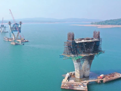
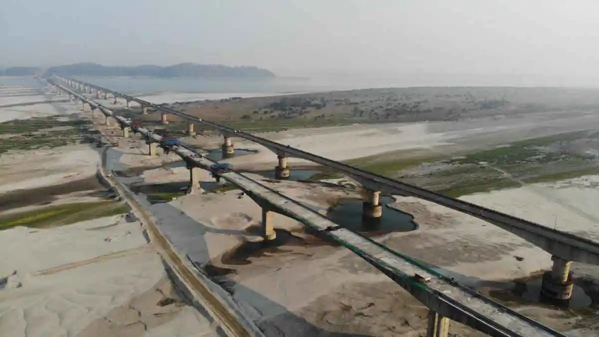
Brahmaputra is one of the longest river in Asia with a total length of 2880 km & out of which 920km (approx.) lie in India. The New Brahmaputra Bridge @ Tezpur is one of the most challenging one, in the attempt to bridge the river Brahmaputra once again. In India the Brahmaputra is the only river which had not been bridged till the end of 1962 along in its entire length. Bridging river Brahmaputra has always been a challenging task. The river has been traditionally considered extremely difficult to bridging due to its ferocious & unpredictable behavior coupled with Flash Floods & high current/ turbulence, wide spread erosion of the banks, change in island configuration.

This Project road starts from Ch. – 0.00 km of NH-37A at Kaliabor Tiniali and ends at Ch. – 17.30 km of NH-37A at Dolabari junction comprising total length of 17.30 km including construction of New Brahmaputra Bridge of 3.015 Km length

This Project is a component of the SARDP-NE Project. The project road passes through Nagaon and Sonitpur District in Central part of Assam.

The scheme has been included by the Ministry of Road Transport & Highways in SARDP-NE Phase A with the aim to create 4-lane connectivity to Itanagar, the capital city of Arunachal Pradesh.

Construction of New Brahmaputra BridgeFigure: 1 Approximate Location of Projected Highway

Construction of New Brahmaputra Bridge

Construction of New Brahmaputra Bridge

SALIENT TECHNICAL FEATURES:

` Project Name 4-Laning of NH-37A from Km 0.00 (Kaliabor Tiniali road junction) to Km 17.300 (Dolabari road junction) including construction of New Brahmaputra Bridge on EPC basis in the state of Assam under Phase A of SARDP-NE.
1 Authority National  Highways  &  Infrastructure  Development
Corporation Ltd.  (NHIDCL)
3rd Floor, PTI Building
4 – Parliament Street, New Delhi -110001
2 Authority’s Engineer SA Infrastructure Consultants Private Limited
Corp. Off.: 1101A, 11th Floor, Tower A-II, Corporate Park, Plot No. 7A/1, Sector 142, Noida 201301, Uttar Pradesh, India
3 Proof Indian Institute of Technology (IIT), Delhi.
Consultant Hauz Khas, New Delhi – 110016, India
4 Design B & S Engineering Consultants Pvt. Ltd.
Consultant 315-316, Vishal Chambers, P-1,
  Sector-18, Noida, U.P. – 201301.
5 Contractor M/s Gammon India Ltd. – SP Singla Constructions Pvt. Ltd.  (JV)
6 Contract Rs. 588.95 Cr
Value
7 Type of Engineering Procurement Construction (EPC)
Contract
8 Appointed Date  /Commencement date: 29th November’ 2014
9 Original/ Revised Construction Period  48 months/ 72 months
10 Original/ Revised Completion Date  28th November’ 2018/ 9th November 2020
11 Maintenance period 4 years commencing from the date of the Provisional Certificate

SCOPE OF WORK:

Sl No DESCRIPTION REMARKS
1 Details of Project Highway Existing Proposed
a Highway Length 17.30 km. 16.42 km.
b Bypasses Length 0.00 0.00
c Realignment Length 0.00 0.88
  Sub Total 17.30 km. 17.30 km.
d Service/Slip  Roads 1.2 km. 1.2 km.
2 Details of Project Structures Existing Proposed
a Flyovers / Elevated Structures - -
b Major Bridges 02 nos. 02 nos.
c Minor Bridges 08 nos. 08 nos.
3 Culverts    
a Slab Culverts 03 nos. -
b Box Culverts - 06 nos.
c Pipe Culverts 16 nos. 13 nos.
  Sub Total 19 nos. 19 nos.
4 Project Facilities / Miscellaneous  
a Grade Intersections 04 nos. Major and 20 nos. Minor
b Bus Bays 04 nos.
c Truck Lay Bays Nil
d Toll Plazas 01 no. at Chainage 07.05 km. (Existing)

Technical Details
  • New Brahmaputra Bridge - Total Length = 3.015 Km + 0.025 Km ( additional span ) = 3.040 Km
  • Span Length - 120 m
  • Total No of Span- 27
  • Foundation - Well Foundation/ Pile Foundation
  • Super Structure – Balance Cantilever Box Girder (RCC) Comprising of 9 Module
    • End Module = 67.5+120+60
    • Other Module = 60+120+120+60
  • Highway = 14.285 Km
Major Bridge (New Brahmaputra Bridge)
Foundations/ Pile Foundation

24 nos of Well Foundations and 4 nos of Pile Foundation.
Well foundations:
Depth : 56 m to 59 m
Type : Circular
Pile Foundation:
1. Depth : 32 m to 44 m
2. Dia : 2 m

1. Well Foundations
Cutting Edge & Steel strakes: The cutting edge is made up of ISA 100, structural steel plates 16 mm thick in outer face. The total qty of all cutting edges are 32.30 MT. These are placed on dry surface after leveling the required area.

Well Curb: The well curb is of Circular shape of height 5.1 M from bottom. The inner & outer side of well curb 3.075M from bottom. The well curb is concreted with M30 grade.

Sinking: Sinking of wells were carried out by means of conventional sinking method using crane & grabs. The well were sunk by means of Crane & grabs up to a depth of 56.20 M from RL 61.2M. The strata met with during sinking of the wells were Fine sand / sand mixed clay / sand mixed gravels / Rock etc.

Steining: The steining height of wells are A1 – 55.789M, P1to P23 – 52.95M (Avg.), with thickness 2.0 M. from bottom of well to MSL (RL 23.56M) and thickness 1.5 M. from MSL (RL 23.56M) to Well Cap bottom RL (61.20M) and the steining was cast in lifts with M30 /M35 grade of concrete.

Bottom Plug: After the Cutting Edge of well Fdn reaches the founding level, well was plugged under water with M25 grade concrete & 10% extra cement for under water concreting.

Well Cap: Well cap of 1.8 M depth was cast with M35 grade concrete. The quantity of concrete of each well cap is 90.43 cum.

2. Caisson
There are 9 Nos. of Caissons P15 to P23.

The details of caisson are as under.
Sl. No Well No Length Caisson Bed Level Depth of water Grade of Concrete
2.1 P15 7.875M 55.230M 4.200M M-35
2.2 P16 7.875M 55.335M 5.585M M-30
2.3 P17 5.475M 55.630M 3.815M M-35
2.4 P18 9.475M 54.540M 5.210M M-35
2.5 P19 9.475M 54.400M 5.340M M-30
2.6 P20 9.475M 53.250M 6.475M M-35
2.7 P21 12.075M 54.310M 5.060M M-35
2.7 P22 9.075M 54.210M 5.250M M-30
2.9 P23 9.075M 55.160M 4.100M M-35

3. Pile Foundation

The dimensions of pile & caps are as follows:
Sr. No Description Nos of Pile Dia of Pile Depth of Pile Size of Pile Cap   /Abutment Cap
L x B x H
3.1 P24 8 2M 43.4m 17.5x7.5x3.2
3.2 P25 6 2M 43.95m 12.5x7.5x2.95
3.3 A2 2 2M 34.393m 10.0x3.8x1.5
3.4 A2/1 2 2M 32.073m 10.0x2.5x1.5

4. Pier / Pier Caps & Abutment / Abutment Caps
There are 2 Nos. of trapezoidal abutment A1 & A2 & 25 nos of rectangular piers P1 to P25 (Each Well location has 2 nos of pier). The dimensions of pier, abutments & caps are as follows:

Sr. No Description Height of Pier / Abutment Size of Pier   /Abutment
L x B x H
4.1 A1 &A2 14.798m 5.000 m x1.000 m x 14.798 m
5.2 P1-P25 14.797m 5.00 m x(1.25m /1.35m )x 14.797m

5. Super Structure

Type: Pre-stressed RCC Single Box Girder
The distance between A1 - P1 & P25-A2 is 67.5M, A2-A2/1 is 25.0M and rest 24 span is 120.0m each.
Span Arrangement: 2 x 67.5 + 24 x 120+25 = 3040 meter

Major Quantities of Prime Activities of Structures

SNo. Description Quantity Unit
1) Foundations: 28 Nos
1.a) Well Foundations: 24 Nos
  Fabrication of cutting edge 24 Nos
  Cutting Edge placing / erection 15 Nos
  Floating, lunching & grounding of caisson 09 Nos
  Well Curb 24 Nos
  Well Steining 1347.53 RM
  Well Sinking 1347.53 RM
  Bottom plugging after reaching the founding level 24 Nos
  Non recoverable beam and slab placing for sealing the  dredge hole of well foundation 24 Nos
  Well cap 24 Nos
1.b) Pile Foundations: 04 Nos
  Pile 18 Nos
  Length of Pile 743.83 RM
  Pile Cap 04 Nos
2) Substructures:    
  Piers 25 Nos
  Abutment 3 Nos
3) Super structures:    
  Pier Head 175 RM
  Adaptor Unit 162.5 RM
  Balanced Cantilever (CLC) 2602.5 RM
  Stitch Units 68 RM
  Central Hinge Units 32 RM
  Central Hinge Bearing 16 Nos
  Pot PTFE Bearing 06 Nos
  Modular Expansion Joint    
  i) 4 Seal 96 RM
  ii) 2 Seal 24 RM

Sl. No ITEMS Unit TOTAL QUANTITY
1 Concrete. Cum 117475
2 Reinforcement Steel. MT 9675
3 Cement. Bag 939800
4 Coarse Aggregate. Cum 104553
5 Sand. Cum 58737
6 Sinking. RM 1342.82
7 Structural (For Fabrication of Cutting Edge, Caisson etc.) MT 4111
8 HT Strand MT 1450

Well Foundation & Sub Structure Construction Sequence
  1. Cutting Edge placing / erection.
  2. Well Curb.
  3. Well Steining / Well Sinking.
  4. Bottom plugging after reaching the founding level.
  5. Non recoverable beam and slab placing for sealing the dredge hole of well foundation.
  6. Well cap.
  7. Piers/ Abutment.
  8. Pier head.
  9. 1st Segment
  10. Balanced Cantilever (CLC)
  11. Stitch Units/ Central Hinge Units.
Method of Constructing Well Foundation
1. Cutting Edge placing / erection
Fabrication as per drawing up to required height at fabrication yard


Bending of cutting edge Angle as per the radius mentioned in drawing by Hydraulic Jack at Fabrication Yard.

Construction of New Brahmaputra Bridge

Placing of bent angle and straight angle as per drawing over the already made pedestals fixing of skin plate on the outer and inner side on the bent angles.

Bending of cutting edge Angle as per the radius mentioned in drawing by Hydraulic Jack at Fabrication Yard.

Erection of Cutting Edge at location
  • Cutting Edge is generally placed in Natural Island or in built up Island.
  • Natural Island is formed naturally after siltation of soil / sand in the river. It is most suitable for placing of cutting edge of well.
  • Where the depth of water is within 3m to 5m and where the water is stagnant, in that case island is been made for placing of Cutting Edge.
  • The island is constructed by driving two rows of Bamboo / Balli piles at a spacing of 200mm for Bamboo and 400mm for Balli piles.
  • A minimum distance of 0.75m is kept between two rows of Bamboo/Balli.
  • Each pile should be driven at least 1/3 of water depth below bed so as to have a sufficient grip.
  • Required nos. of horizontal and cross bracings are fixed with vertical piles for strengthening the Island.
  • After that Bamboo matting is been fixed along the inside faces of the ballies and the space between the matting are filled up with puddle clay or with sand bags.
  • Sand bags are dumped on the outside of the outer row of piles to provide supports to the piles.
  • The space enclosed by the bamboo or ballie walls is filled with sand upto the proposed top level of the Island.
Construction of New Brahmaputra Bridge

2. Well Curb
  • Fixing of inner shuttering above Cutting Edge up to 3.075 mtr. Height.
  • Reinforcement steel fixing up to the required height.
  • Outer shuttering plates fixing.
  • Concreting.
3. Well Steining / Well Sinking

Construction of New Brahmaputra Bridge
  • After concreting of well curb, it is kept undisturbed for 3 days. Then inner, outer shuttering plates are removed and manual sinking is done.
  • Fixing of formwork and reinforcement for well steining (3 mtr. Lift).
  • Concreting (3 mtr. Lift).
  • After setting of concrete, deshuttering (3 mtr. Lift) is done.
  • Sinking (3 mtr. Lift) is executed by using crane.
Construction of New Brahmaputra Bridge

4. Bottom plugging after reaching the founding level
  • After the cutting edge reaches the founding level, bottom plugging is done by Tremie pipe method.
Construction of New Brahmaputra Bridge

5. Non recoverable beam and slab placing for sealing the dredge hole of well foundation
  • After completion of bottom plugging, the rest of the well steining is filled up with water upto the bottom of well cap.
  • Well cap soffit shuttering to be done by placing non recoverable beam and slabs.
  • After completing the soffit shuttering, reinforcement and outside shuttering concreting to done.
Construction of New Brahmaputra Bridge

6. Well Cap
  • After completion of non-recoverable soffit shuttering, fixing of well cap reinforcement and shuttering is done, followed by concreting.
Construction of New Brahmaputra Bridge

Construction of New Brahmaputra Bridge

7. Piers/ Abutment
  • After the completion of well cap casting, reinforcement and shuttering works for twin piers are done.
Construction of New Brahmaputra Bridge

8. Pier head
  • After the completion of piers, pier head soffit shutters, scaffolding, supporting arrangement and concreting to be erected.
Construction of New Brahmaputra Bridge

9. 1st Segment
  • After the completion of pier head, 1st segment shutters, scaffolding, supporting arrangement and concreting is done.
Construction of New Brahmaputra Bridge

10. Balanced Cantilever (CLC)
  • After completion of 1st segment the CLC gantry (4m. seg) is erected over the box girder. Then, Casting of 2nd & further segment with CLC gantry is done as per drawing.
Construction of New Brahmaputra Bridge

11. Stitch Units/ Central Hinge Units
  • After completion of all CLC segment the CLC gantry to be removed over the box girder. Then, Casting of Stitch Units/ Central Hinge Units is done as per drawing.
Construction of New Brahmaputra Bridge

Methodology Adopted for Caisson Foundations
Fabrication of Caisson: Well foundations located in deep water is being constructed using steel floating caissons. Fabrication of caisson upto the required height for floating is done at fabrication yard and then cut into suitable Modules/segments as per drawing.

Construction of New Brahmaputra Bridge

Arrangements for floating caisson: Cofferdam is prepared for Launching bed of Caisson near river bank. Location is selected by proper survey and considering the depth of water along the towing path. Steel caisson of required height is fabricated/ assembled in this bed. After checking the water tightness of caisson grabbing is done from inside the dredge hole and as well as from outside of caisson. Sinking of the caisson is done as per reqd. draft. Dismantling of coffer dam is done to allow water to enter in the assembly area of Caisson. Grabbing is done continuously till the caisson floats into water.

Construction of New Brahmaputra Bridge

Towing of caisson to required location: Once the caisson starts floating, the same is towed to its desired location. After reaching the actual foundation location, the caisson is secured in position by using wire ropes connected to floating buoy.

Construction of New Brahmaputra Bridge

Grounding of caisson & Sinking: Concrete placed in the caisson, quantity of which is poured as per detailed designs. With this the caisson gets submerged further into water. Next lift of caisson is then built by joining the pre-fabricated modules/segments of each lifts. Filling of concrete and building of caisson continued till the caisson rests on the river bed. Before grounding of the caisson its alignment is rechecked. Once the caisson touches the bed level, further activities is carried out as normal well foundation. Muck inside the dredge hole is removed using crane Mounted on Barge. (Refer tentative sketch no. J&G-C-PP/03 & J&G-C-PP/04, which may be changed as per site conditions).

Construction of New Brahmaputra Bridge

Construction of New Brahmaputra Bridge

Construction of New Brahmaputra Bridge

As the caisson sinks further, next height of steining is cast. This process continued till the cutting edge reaches the founding level.

Methodology Adopted for Pile Foundations
General: Bored cast in-situ concrete piles of circular cross section of 2000.0 mm diameter is formed by boring into the termination level as indicated on GFC drawings or as directed by Engineer/Consultant at site. Concrete is of grade designation as specified in GFC drawings for the bored cast in-situ piles. Concrete for piles is produced only by weigh batching the ingredients as per Drgs & MORT&H specifications.

Cast in-Situ concrete by Tremie
Grade of concrete M-45
Minimum cement content 430Kg/Cum
Minimum Water cement ratio 0.35
Slump (mm)as measured at the time of placement 150-210

Formation of Pile bores: Pile bores up to the specified depth is executed by Winch Machine Method. The pile location is marked on the ground using 6 – 8mm steel bar, 15-20 cm long. The Winch machine is correctly aligned to the impression. On aligning Winch machine, boring is carried out to the required depth and then MS liner of suitable length is placed in the pit concentric to the pile point. The liner is then pressed inside with the arrangements available in the platform.

The liner is then added and driven till refusal. The boring operation continued till the desired founding level. The mud removed from the bore is disposed as per site condition.

Bentonite & its specification
Bentonite suspension is of following specification as per IS: 2911-part-1/sec2 2010&( MORT&H 5th Rev.)
Density of fresh prepared bentonite suspension: 1.03 to 1.1 g/ cc (1.05g/cc MORT&H 5th Rev.)

a) Marsh Viscosity: 30 to 60 seconds
b) PH Value: Between 9.0 to11.5 (9.5 to12.0 MORT&H 5th Rev.)
c) Sand Content: Less than 7%
d) Silt content: Less than 1%
e) Liquid limit: Not less than 400%

MS Liner
Fixing of MS liners (thickness 16mm & 12mm as pre site condition) with Inner Dia. 2000 mm done & then driving done after fabrication at the site during boring.

Control of Alignment
The working platform and gantry for arrangement of pile is done after checking and maintaining the verticality of the bore. In case, if required, verticality can also be checked using plumb bob and spirit level. Piles is installed within permissible limits according to the drawings.

Bored Cast in Situ-in-Pile Installation
For the construction of Bored Cast-in–situ pile installation, Winch Machine / Hydraulic Rotary Drilling Rig (MAIT) machine is used.

Final post bore cleaning/ Flushing of bore
Cleaning bucket attached to the Kelly is used for cleaning the bore. wherever, bentonite slurry is used, after using cleaning bucket, the bore is flushed with fresh bentonite slurry. Flushing is continued till coarse materials cease to come out with the overflowing fluid. The finer materials normally remains suspended in the fluid. The density of bentonite after contamination with deleterious material in bore hole may rise up to 1.25g/ml. This should be brought down to at least 1.12g/ml by flushing before concreting. The final depth is checked with a sounding chain.

Placement of reinforcement cage
After ensuring the depth of the bore, pre-fabricated reinforcement cage as per the drawing is lowered followed by placing of the tremie pipe and steel funnel attachment. The rebar cage is lowered into the bore by gravity only with the P & H crane. For piles requiring multiple length of rebar cages, the first length of cage is lowered and held with top of the bars adequately strengthened above the bore on which upper cage is placed in position, lapped and joined in place and then cage is lowered.

Pile Concreting
Requirements for concreting piles

Pile concreting is done using tremie pipe method. Only fresh batched concrete is used and the concreting done continuously without interruption. Tremie pipe concreting is done as per IS: 456 and IS: 2911 (Part-I/Sec-2) using a pipe of minimum 200mm diameter. The steel hopper at the top shall have a volume greater that the tremie pipe volume. The hopper and pipe shall be clean of dust, debris etc., and shall be watertight. Concrete placing into the hopper shall be facilitated using suitable ramps for direct pour from the transit mixers. In case of inaccessible locations, concrete is alternatively be placed into the hopper by concrete pump. Subsequent pouring of concrete is maintained continuous as required till the pile bore is cast to the specified height. The bottom of tremie pipe shall always be inside concrete forming watertight system. The tip shall be minimum 0.600 to 1.0 meters inside concrete depending upon rate of pouring concrete. The tremie pipe shall be withdrawn in stages as and when concrete builds up in the bore. Particular care shall be taken when vertical movement is imparted on tremie pipe to force concrete down into the pipe and also when tremie pipe is raised so that the rebar cage is not disturbed from its position.

All the piles shall be concreted to a level at least that of the cut-off level. The top of concrete in a pile shall be brought above cut-off level up to a minimum height of 600mm to permit removal of all laitance and weak concrete as per IS 2911/Part1/sec-2-2010 as per clause no 8.4.4, so that the concrete at the cut-off level shall be dense and sound..

Pile cut-off and extension
Excavation is carried out 50mm up to the bottom of the pile cap with necessary shoring. The pile is chipped and the debris is carted away. During chipping and trimming off piles, care shall be taken to avoid damaging of concrete. Chipping of pile shall be done till sound concrete is met with or up to specified cut-off level. If stripping of pile concrete is required to be done to a level lower than the specified cut-off level on account of defective concreting, workmanship etc., the pile shall be built-up with good concrete of specified grade.

On completion of pile cut-off, all exposed reinforcement shall be cleaned.

Reinforcement
All reinforcement are used as per the approved drawings. The reinforcement is assembled and tied together and made up into cages sufficiently rigid to withstand handling without any damage and distortion. Concrete cover to all the reinforcement, including lateral hoops shall be 75mm.

Equipment &Materials details
  • Pile Winch Machine.
  • Batching plant Min. 30.0 cum/hr capacity.
  • Transit mixers 6 cum capacity.
  • Tremmie pipes of 265mmØ and steel hopper/funnel for concreting, Bailer, Tripod/ same arrangement, Liner cap, Rock Cutting Chisel, Winch Drum, Vibro Hammer& Monkey Liner Driving, and Flushing Head & Mud Pump.
  • Water Tank
  • Crane P & H, Hydra, Trailer /Truck
  • Rebar cutting & bending m/c
  • Chisel-Chisel of required diameter shall be used.
  • Power generator of suitable capacity.
  • Total Station, Auto level, leveling staff etc.
  • Welding Machine and electrode.
  • MS fix Liner as per site conditions.
  • Bore Pile Bucket, Mud Bucket Drilling, Drill bits & Auger boring machine.
  • Measuring steel tape, line rope.
  • Cube molds, slump cone, Trays, Mud Balance/Hydrometer & 1000ml Jar.
Materials
  • Concrete: - Concrete is as per approved drawing, the maximum size of coarse aggregate is restricted to 20mm. Concrete is produced in Batching Plant as per the approved mix design, M-45 (Pile) as per Drawing.
  • Water: - Water is used from approved source.
  • Reinforcement: - Reinforcement steel for piling is as per grade specified in contract and Conforming to IS: 1786, Only Fe500D TMT reinforcement and as per approved Drawing is used.
  • Cement: - Cement OPC -43 Grade is used for piling with prior approval from Engineer. MTC/Lab Test certificate is maintained and various laboratory tests conducted for Cement.
  • Course & Fine Aggregate: - Course & Fine Aggregate conforming to IS: 383& 2386 is used for Piling. Gradation of combined aggregate is in accordance with IS: 383& 2386. Various mechanical properties of coarse aggregates and properties of Fine aggregates are conforming to IS: 383& 2386 and tests are conducted as per relevant test codes.
Construction of New Brahmaputra Bridge

Methodology Adopted For Pier / Pier Head & Abutment / Abutment Cap
Pier / Pier head & Abutment / Abutment Cap
Pier / Abutment works
: Pier / Abutment wall is cast in suitable Lifts as per site feasibility at each location with suitable staging and shuttering arrangement as per approved drawings and specifications. Concrete Pumps / Boom placer are used to place the concrete. Construction joints if any are planned at locations as shown in the drawings. Suitable treatment is given to the construction joint before pouring fresh concrete. Curing is carried out as per specifications. Access arrangement for inspection and safe working of labor during fabrication, erection of reinforcement, shuttering and placing of concrete is done as per specifications.

Construction Methodology – Pier / Abutment.
  • Center line marking at top of the Well cap.
  • Reinforcement fixing for Pier / Abutment wall.
  • Shuttering for pier starter.
  • Checking of center line of Pier starter.
  • Concreting of Pier Starter.
  • Fixing of Formwork for Pier / Abutment wall.
  • Proper support fixing and checking of alignment of Pier formwork.
  • Concreting of Pier by using Concrete Pump / Boom placer.
  • De-shuttering of Pier / Abutment wall formwork.
  • Curing of Pier.
Construction of New Brahmaputra Bridge

Construction of New Brahmaputra Bridge

Pier head / Abutment Cap Works.
After casting of Pier / Abutment staging & shuttering is erected for Pier cap / Abutment cap with reference to the layout. The reinforcement for pier cap fixed at the top of pier / Abutment reinforcement after casting of Pier & placing of bottom shuttering. (Please refer tentative sketch No. - PP/06 which may be changed as per drawing and site conditions).

Construction Methodology – Pier head / Abutment cap & 1st segment
  • Erection of staging arrangement with the help of supporting brackets with respect to survey layout.
  • Fixing of hinge with bracket of both cantilever side and stool fixing with ISMB Girder for deck, after staging fixing above girder and bracket.
  • Placing of soffit, web, cantilever & deck shuttering for Pier head & 1st segment.
  • Fixing of Reinforcement steel.
  • Fixing and alignment of side shuttering.
  • Concreting of Pier head / Abutment cap by using Boom placer/ concrete pump.
  • De-shuttering of Pier head side formwork.
  • Curing of Pier head/Abutment cap.
  • HT Strand cutting, threading, Jack fixing and stressing to be done before dismantling of supporting arrangement of Pier head and 1st segment.
  • Dismantling of Bracket, Girder, staging and shuttering.
Construction of New Brahmaputra Bridge

Super Structure
Methodology of Cantilever construction

  1. Before concreting the deck slab 50 mm long sleeve is fixed as per drawing which shall be used for fixing wheel guide locking for CLC gantry erection as per drawing.
  2. After stressing of 1st segment the CLC gantry (4m. seg) is erected over the box girder.
  3. Casting of 2nd segment with CLC gantry is done as per drawing.
  4. Stressing is done after 3days of 2nd segments after concrete attains required strength 42N/MM2.
  5. Shifting the gantry is done for further casting of cantilever box unit as per construction sequence as per approved drawing.
  6. The same method is continued for the balance segment to be cast.
  7. Casting of continuity unit (0.739 m) is done by using suspender platform resting on the tips of both the box girder.
  8. Cables that are been stressed shall be grouted as per IRC-18:2000
  9. After completing the segments cast by CLC gantry the gantry is dismantled and erected on another pier and the same process continued.
  10. Concreting is done either by Conc pump/ Boom placer.
  11. 13 sets of CLC gantry namely Gantry A, B,C,D,E,F,G,H,I,J,K,L and M is used as mentioned below.
    1. Gantry A: P 8 and P 15
    2. Gantry B: P3,P17 and P19
    3. Gantry C: P7 and P 16
    4. Gantry D: P2,P20 and P18
    5. Gantry E: P6
    6. Gantry F: P5
    7. Gantry G: P4
    8. Gantry H: P1, P9
    9. Gantry I: P10, P21
    10. Gantry J: P11, P22
    11. Gantry K: P12, P23
    12. Gantry L: P13, P24
    13. Gantry M: P14, P25
  12. After completion of each unit of CLC box girder the deflections at the tip of the unit is checked to take corrective action if needed.
  13. During the movement of gantry and concreting all the safety precaution is taken care of. Safety personnel to be present to monitor during the execution of all critical activities.
The method statement for prestressing for Cantilever box girder is given here below:

Method Statement for Prestressing Activities
Purpose: To Laydown Defined Procedure for Decoiling & Cutting, Threading, Prestressing Operations and Grouting.
I. HT Strand Decoiling and Strand Cutting
  1. Shift the coil from Godown to the cutting yard carefully with the help of Hydra & keep it upright inside the De-coiling cage. De-Coiling cage should be properly wrapped with the Hessian cloth to avoid rubbing of strands while decoiling.
  2. Note down the Coil number and other details viz. Weight of coil, Modulus of Elasticity and Cross Sectional Area of Strand.
  3. Decoil the strand to the given cutting length over properly laid platform (Platform should be free from any other material) and cut the strand with the help of Electric Grinder.
  4. Repeat the procedure for cutting the strands for all the remaining cables of given cutting length.
  5. Proper care should be taken while cutting that each strand should be of same length of every cable. Individual variation in the cutting of strand should not be more than +/- 25 mm. Also all ply in a strand shall in one plane.
  6. The balance coil in the cage after days work should be covered properly by plastic Tarpaulin and tied properly.
II. Threading
  1. The cut cable should be checked for its cleanness before threading.
  2. Winding the PVC tape at one end and inserting it inside the duct to avoid any damage to sheathing pipe inside the duct shall do threading very carefully.
  3. Sufficient number of labours to be engaged for threading so that during threading operation no strand should remain in touch with the ground.
  4. Repeat the above procedure of threading for remaining cables.
III) Fixing of B.P. & Grips
  1. Clean bearing plates & Grips with petrol.
  2. Clean the strand in the jacking length portions with the petrol before fixing the jack.
  3. During fixing of bearing plate care should be taken that every strand will be @ 1150 mm long away from the face of Guide cone.
  4. Fix the grips inside the Bearing Plate with the help of Pipe Hammer.
IV) Jack Fixing
  1. Fix the jack to both the ends of the cables by using master grips.
  2. Connect the Hydraulic hose pipes of the EOHP Pump with the K 500 Jacks. Now the entire assembly is ready for stressing operation.
V) Stressing Operation
  1. Start both the EOHP Pumps simultaneously & apply the pressure to remove the slag. Now pressure gauge shows lifting of needle above the zero mark reading.
  2. Start both the EOHP Pumps simultaneously & apply the pressure in the increment of 50 Kg/Cm2 & corresponding elongation is noted in the prestressing formats. Zero error correction shall be calculated @ 200 Kg / Cm2 .
  3. Apply the required pressure till the required elongation is achieved.
  4. Once required elongation & pressure is achieved apply the blocking pressure to lock the cable.
  5. Start releasing the pressure gradually till dial gauge shows zero – zero reading.
  6. After releasing operation is over measure and note down the slip in the stressing formats.
  7. Start the de-wedging operation and remove the jack and its accessories.
  8. After removing the Jack proper identification mark is to be done @ 300 mm away from face of guide cone for the measurement of slippage after 24 Hrs.
  9. Repeat the above procedure for the stressing of remaining cables.
VI) Calibration

Once in a six-month all the gauges shall be calibrated.

VIII) Saftey Precautions
  1. Place the steel barrier behind the cables to be stressed at proper distance away from both the ends of jacks so as to avoid possible accident due to throwing of object such as master grips/ Ply etc. with the great speed due to any unforeseen slippage/ Breaking of strand etc.
  2. Avoid the people to stand or move behind the jack during stressing operation.
  3. Warning sign shall be displayed during stressing.
  4. Supervising staff that is engaged in measuring the elongation and labours working in the area should stand away from the side of jack.
IX) Cable Cropping And Grout Cap Fixing
  1. After measuring 24 Hrs slip the cropping of strands to be done 30 mm away from the locked grips.
  2. Clean the Bearing plate & cropped strands by Petrol to remove rust.
  3. Fix the Grout cap at both ends of cable.
  4. Above procedure for all the remaining cables to be repeated.
  5. Grouting should not be delayed more than 14 days after completion of stressing operation.
X) Grouting
Operation
  1. Clean the cable by injecting water through grout pump keeping water pressure @ 5 Kg / Cm2 & check for Leakage. If found same to be rectify.
  2. Remove the water from Duct by Compressed air.
  3. W/C for the grouting operation is 0.45.
  4. As per the ratio water is first poured into the drum then cement, Admixture & start Agitator for preparing thoroughly blended grout @ 2 to 3 minutes.
  5. Temperature of the grout to be noted should not be more than 250c.
  6. Start passing Grout through the Duct Grout pump by keeping pressure @ 3 Kg / Cm2 from one end & check the consistency of grout from other end should be approximately same as of at Inlet.
  7. Once we get required Consistency of Grout close the get valve stop Pump open the air vent then start Developing Pressure & observed it in the Dial-gauge.
  8. Stop the pump after getting 5 Kg / Cm2 pressures keeping it for @ 1 minute.
  9. Close the Gate Valve at live end & release the pressure.
  10. Repeat the same procedure for other cables.
XI) Records
The following records shall be kept
  1. Calibration report for pressure gauge
  2. Prestressing record
  3. Cube test result for concrete
  4. Cube test result for grout
  5. Record for deflection
Road Work

Construction of New Brahmaputra Bridge

Typical Cross Section of Road (4 Laning)

The DBM Length of 7.765 Km (4 laning) is completed out of 14.285 Km of total road length.

Major Quantities of Prime Activities of Road
Sl. No ITEMS Unit TOTAL QUANTITY
1 Earthwork Cum 948618
2 GSB Cum 91555
3 WMM Cum 73912
4 DBM Cum 33192
5 BC Cum 11333
6 Stone Pitching Sqm 48000
7 Filter media Sqm 21000
8 Concrete Cum 8588
9 Reinforcement Steel MT 64

Challenges Encountered and Remedial Measures Adopted
Seasonal Change in the course of river and water depth at different locations resulted in change in construction methodology and materials / plant & machineries movement / logistics to desires locations:


1st Working Season (2015-16)

Construction of New Brahmaputra Bridge

2 Km (Upstream & Downstream) of service road was made from A1 well location to the P14 well location, which was made for transportation of concrete, materials & manpower. The service Road was washed out due to flash flood on 08.04.2016.

Concreting method:
  • Well Location P2 to P9: Concrete transported from batching plant (South Bank) to Well P1-P9 location by T.M.
  • Well Location A1, P1 & P10 to P14: Concrete transported from batching plant to desired Well location by T.M.
2nd Working Season (2016-17)

Construction of New Brahmaputra Bridge

In the 2nd season, 9 nos of Caisson was successfully launched and grounded in the Well location P15 to P23. Concrete work of Caisson was done by barge mounted TM.

1.05 Km service road was made from A1 well location to the P9 well location, which was made for transportation of concrete, materials & manpower. The service Road was washed out due to flash flood on 24.04.2017.

Concreting method
  • Well Location P2 to P9: Concrete transported from batching plant (South Bank) to Well P2-P9 location by T.M.
  • Well Location A1 & P1: Concrete transported from batching plant (North Bank) to desired Well location by T.M.
  • Well Location P15 to P20: Concreting operated from Batching Plant (South Bank) to Transit Mixer to Concrete Pump-I near Well P9 location at island and then concrete was loaded to barge mounted TM and transported to desired location.
  • Well Location P20 to P23: Concreting operated from Batching Plant (North Bank) to Transit Mixer to Concrete Pump-I near Well P25 location at island and then concrete was loaded to barge mounted TM and transported to desired location.
3rd Working Season (2017-18)

Construction of New Brahmaputra Bridge

In the 3rd season, 1.95 Km service road was made from A1 well location to the P16 well location, which was made for transportation of concrete, materials & manpower. The service Road was washed out due to flash flood on 13.05.2018.

Concreting method
  • Well Location P2 to P9, P15 & P16: Concrete transported from batching plant (South Bank) to Well P2-P9 location by T.M.
  • Well Location A1, P, P10 to P14: Concrete transported from batching plant (North Bank) to desired Well location by T.M.
  • Well Location P17 to P20: Concreting operated from Batching Plant (South Bank) to Transit Mixer to Concrete Pump-I near Well P9 location at island and then concrete was loaded to barge mounted TM and transported to desired location.
  • Well Location P20 to P23: Concreting operated from Batching Plant (North Bank) to Transit Mixer to Concrete Pump-I near Well P25 location at island and then concrete was loaded to barge mounted TM and transported to desired location.
4th Working Season (2018-19)

Construction of New Brahmaputra Bridge

In the 4th season, 2.6 Km service road was made from A1 well location to the P16 well location, which was made for transportation of concrete, materials & manpower. The service Road was washed out due to flash flood on 04.05.2019.

Concreting method
  • Well Location P2 to P8, P15 & P16: Concrete transported from batching plant (South Bank) to Well P2-P9 location by T.M.
  • Well Location P9 to P14: Concrete transported from batching plant (North Bank) to desired Well location by T.M.
  • Well Location P17 to P20: Concreting operated from Batching Plant (South Bank) to Transit Mixer to Concrete Pump-I near Well P9 location at island and then concrete was loaded to barge mounted TM and transported to desired location.
  • Well Location P20 to P23: Concreting operated from Batching Plant (North Bank) to Transit Mixer to Concrete Pump-I near Well P25 location at island and then concrete was loaded to barge mounted TM and transported to desired location.
Ongoing 5th Working Season (2019-20)

Construction of New Brahmaputra Bridge

In the current season, 2.5 Km service road has been made from A1 well location to the P17 well location, which was made for transportation of concrete, materials & manpower.

Concreting method
  • Well Location P4 to P6, P15 to P17: Concrete transported from batching plant (South Bank) to desired location by T.M.
  • Well Location P18 to P20: Concreting operated from Batching Plant (South Bank) to Transit Mixer to Concrete Pump-I near Well P9 location at island and then concrete was loaded to barge mounted TM and transported to desired location.
  • Well Location P21 to P25: Concreting operated from Batching Plant (North Bank) to Transit Mixer to Concrete Pump-I near Well P25 location at island and then concrete was loaded to barge mounted TM and transported to desired location.
Hindrances During Execution of Pile Foundation of P24 & P25 Locations
The design and Drawing of Pile foundation was approved by Authority & Authorities Engineer after review of SSI Report

After getting the approved pile foundation drawings on 26/02/2018, team was mobilized for both locations i.e. P24 & P25 locations. Arrangements were made, platform was erected to start activity at P25 and platform / jetty construction was initiated for P24 piling. After erection of platform at P25 boring for 1st pile was taken on 13.03.2018. After going 15.4m (RL 44.200) depth, boulder crated gabions were encountered & work came to stop. On investigating, it was found that these boulder crated gabions were used earlier for the protection of scouring of Well Foundation P2 to Abutment A1 of Existing Kaliabhomora Bridge, 80m upstream of proposed New Brahmaputra Bridge. We took up another Bore i.e. Pile No 3, but unfortunately here also after going 3m depth (RL 52.00), boulder crated gabions were encountered. It totally jeopardized the progress & planning of work. In the meantime water level of river was upsurge and work stopped in that session i.e in May’18.

The Hindrance of P25 was also shared with Design Director M/s B & S Engineering. After lot of studies, they suggested that there is one option that we have to modify the Super structure module P24-P25-A2 so that present P25 location can be eliminated. In the modified proposal of module (P24 to A2), the position of P24 is proposed to be shifted by 15m, P25 by 45 m and A2 by 52.5 m towards Tezpur, but before finalizing it, get the SSI done of New location and get the feasibility of foundation. On carrying out SSI, it was found that the soil parameters were not sufficient to take the load of extended super structure i.e. span length 150m. So, we had to stick to carry out work at earlier foundation location of P24 & P25.

Due to the aforesaid boulder wire crated gabions encountered at both Pile locations, it made variation in the character and nature of the foundation work with longer construction time, type of work, increased efforts and costs, which seems to be impracticable to control the operation to remove boulder wire crated gabions below 15.400 meter (RL44.200) depth of each pile. Pile – driving shall be carried out with conventional Pile – driving winch, which itself is time consuming and bit slow in the above mentioned (boulder crated gabions) strata.

However we worked continuously. As on date at P24, 5 piles are completed (i.e. Pile No. 02, 03, 04, 05 & 06) & boring for Pile No. 01, 07 and 08 is in progress. At P25, 4 piles are completed (i.e. Pile No. 02, 03, 05 and 06) and boring for Pile No. 01 and 04 is in progress but at both Locations Piling progress is severely effecting due to presence of boulder wire crated gabions at P25 and at P24 presence of compacted pebbles and grabbles between RL 36.590 to 23.600 (12.99m) approximately, creating hindrance while driving Liner and chiseling work for pilling.

Reason Behind the Necessity of the 25m Additional Span Between A2 And A2/1
The 25m meter additional span is added (between A2 and A2/1) to cater the earth pressure of this massive height of 33 m of Abutment Wall and alternate type of foundation is not possible i.e. Circular/Double D well due to the strata underneath. The Design & Drawing of Pile and Pile column for Abutment A2 at Brahmaputra River has been Proof Checked by IIT, Delhi and Safety Audit has also been undertaken by Safety Consultant M/s PNG which clearly shows that the requirement of additional span of 25 M is technically necessary.

Hindrances Encountered During The Execution of Well Foundation at P18 & P19
  • Caisson of P18 Well foundation was grounded on 27/12/2016 at RL 54.54m & P19 Well foundation was grounded on 22/12/2016 at RL 54.400m & thereafter sinking activity & building of steining started.
  • On 21/12/2017 i.e. after almost one year, P18 Well foundation’s cutting edge reached RL 8.786m & after that no further sinking received due to hard stratification.
  • For next three month, other than gabbing, Kentledge load as well as chiseling was applied, but no effective result came out.
  • The Well foundation P19 also got stuck at RL 15.284m (i.e. 9.454m above approved founding RL5.830m) since May ’17. On 20/05/2017 CERL reached RL 15.284m & after that no further sinking received due to hard stratification. Large size boulders we started encountering beneath RL 18.000. Apart from Continuous gabbing, Kentledge load as well as chiseling was applied, but no effective result came. We didn’t get sinking in whole working season of 17-18
  • Designer M/s B & S Engineering was approached in Mar’18 to re-visit & check the stability of P18 Well foundation to plug at RL 8.925m i.e. 3.925m above the earlier approved founding level & of P19 Well foundation to plug at RL 15.284m i.e. 9.454m above earlier approved founding RL5.830m.
  • M/s B & S Engineering reviewed the case with actual silt factor 1.3 (as per geotech report for Well P18) and found it safe and revised design was issued by them on 30.03.2018. In the earlier design silt factor was considered as 1.0 and as per that MSL was coming as 23.5, while with actual silt factor 1.3 it got revised to 27.22m. In case of P19 Well foundation M/s B & S Engineering reviewed the case with the silt factor as 1.1 as per geo tech report, value of lacey constant – C as 5.55 (i.e. average value of 4.8 & 6.3, which was considered on minimum side 4.8 in earlier design) and found that the well P19 is safe & can be plugged at the present CERL as it is not sinking further. Here due to above change in parameters, MSL got upward revision from RL 23.5m to RL 29.84m.The revised stability calculation were vetted by proof consultant IIT Delhi & safety consultant.
  • Test boring upto RL (-)11.700 has been already conducted at design stage at the exact foundation locations, hence not required further to ascertain the strata underneath again. Further under water videography at more than 55m depth by sending driver or any means is not possible due to zero visibility at the bottom of well to ascertain the strata underneath
  • As it was month of May 18 i.e. start of Monsoon season, when river water level / river flow remain unpredictable, geo technical investigation by boring was not possible to venture.
  • However, as desired by Clients, the test boring was conducted in both Wells P18 & P19 in the last week of Dec’18 and which got over in 2nd week of February 19 and submitted the report on 15.03.2019 to Clients.
  • The design director re-visited the Design again as per SSI Report and found safe to plug the well P18 & P19 well foundations at present CERL 8.198m & CERL RL 15.284m respectively & accordingly the revised design was approved by M/s B & S Engineering & were vetted by proof consultant IIT Delhi & safety consultant . Finally after substantial deliberations with Clients NHIDCL/ Consultant AE, P18 well was plugged at present CERL 8.198m on dated 08.02.2020. Similarly the Well P19 was also Plugged at present CERL RL 15.284m on 03.03.2020.
Physical Progress as on 29.02.2020
Sl. No. Description of Activity Physical Progress
A New Brahmaputra Bridge
1 Foundation 22 Nos. of Foundation completed out of 27 Nos.
22 Nos. of Well Cap Completed.
4 Nos. of Foundation in Progress.
2 Bearings 3 Nos. completed out of 22 Nos.
3 Sub-structure 22 Nos. of Pier Sub-structure completed.
4 Super-Structure Total 2245.5m length completed out of 3015m.
5 Crash Barrier 474.50 m completed out of 3015m
B New Major Bridge (Kolong river)
1 Foundation Piling & Pile Caps at A1, P1 & A2 completed. 
2 Sub-structure P1, A1 & A2 sub-structure up to Cap completed.
3 Super-structure Deck slab between A1-P1 & P1-A2 completed.
C Existing Major Bridge (Kolong river)
1 Foundation Repairing completed.
2 Sub-structure Repairing completed.
D Minor Bridge All 08 nos. Minor Bridges Completed.
E Culverts 16 Nos of Culverts (4-Lane) Completed.
02 Nos. of Culverts (4-Lane) in progress.
F Road Works Widening of Existing Highway –
10.53 KM of Earthwork upto top of Subgrade completed.
8.37 KM of Granular works for Widening Completed.
6.66 KM DBM completed.
New Carriageway-
Earthwork upto top of Subgrade – 11.18 Km completed.
Granular works  – 9.90 Km completed.
DBM works – 8.87 Km completed.
Protection works  (NCW) & Safety

Problems Encountered & Engineering Solution Adopted
  1. There has been substantial difficulty in planning of Construction Methodology including transportation of concrete in river, coupled with very short working period and high seismicity & remoteness of the area, etc. The water level in the river fluctuates significantly with the season. The lean period / networking last only for about 120 days i.e. December to March. Construction has been carefully planned in such a way that the safe levels of foundations are reached during that period itself.
  2. Transportation of concrete to locations in Brahmaputra river is equally challenging considering change in river course / island configuration in every working season. The concrete is transported to the pumping location at bank of the river by transit mixers. The concrete is then pumped to the well location through pipelines across the river channel. At the Island, concrete is transported to the well location by transit mixer and poured into the well by concrete pipe or placer boom. Whenever pipeline could not be laid due to heavy current in the river, concrete is transported to the location by transit mixers mounted on barges towed by tugs.
  3. One of the most challenging tasks was the construction of 9 Nos caisson foundation for Well P15, P16, P17, P18, P19, P20, P21, P22 and P23 in one season. For this purpose hollow water type steel caissons were pre- fabricated in modules made at fabrications yard in monsoon period and reassembled at the launching bed near both banks in working season. They were then floated in the water and towed to the exact location with the help of tugs. Grounding of caisson was another major challenge faced by the engineers because excessive scouring which took place continuously at the bottom of the caisson near the river bed. Adoption of pre-fabricated caisson had led to substantial saving of construction time in actual , as the working season is very less in Brahmaputra river and in this part of North- eastern region as well. This led to successful grounding of all 9 caisson foundation in one working season and to sink all these 9 well fdn to safe level before the onset of floods.
  4. The Superstructure is being constructed by Cast-in-situ Segmental Construction method with 13 sets of CLC Gantry at a time for fast track construction of Superstructure keeping in view the limited working season & milestones.
  5. During construction of New Brahmaputra Bridge, problem in sinking of two Well foundations i.e. P18 & P19 to designed founding level RL 5.000 & RL 5.830 respectively, encountered, due to massive hard stratification. Well P18 got stuck at RL 8.198m & while Well P19 at RL 15.284m. Besides continuous grabbing, sinking efforts were given by applying Kentledge load and with Chiseling to further sink the Well, the Chisel weight was increased from 3t to 6t & then to 9t to break the Hard stratification, but it also went in vain & 2 working season got completely lost. The stability of Well P18 & P19 was re-visited by Design Director with the actual ground condition (i.e. parameters from SSI reports pertaining to these individual Wells) and arrived at a conclusion that these wells are safe to plug. The revised design was finalized by B&S Engineering & these were vetted from Proof consultant IIT Delhi & Safety consultant M/s PNG .Finally Well P18 was plugged on 08/02/2020 at RL 8.198m & Well P19 was plugged on 03/03/2020 at RL 15.284m.
Construction of New Brahmaputra Bridge

Photographs of Highway

Construction of New Brahmaputra Bridge

Challenges Faced at of Site Due to Dense Fog, Sand Storm & Flash Flood

Construction of New Brahmaputra Bridge

Over View of Under Construction New Brahmaputra Bridge

Conclusion
The completion of this bridge will usher in an era of prosperity and development to Assam and Arunachal Pradesh in particular. This will further strengthen the national security of North eastern region of India. This bridge is of strategic importance as well.

All Construction Bottle Necks Can Be Won By Engineering Solutions
Synergising Aatmanirbhar Bharat and Operational Preparedness: Launch of Indigenous Modular Bridge in Sikkim
Enhanced operational preparedness along the borders and the need to be self-reliant are two major aspects that have seen a substantial impetus over the last few years. The Border Roads Organisation (BRO) has been a key contributor to the infrastructure

Read more ...

Architectural System for Arch Bridges
Dextra India’s architectural systems mainly include Tension Rods and Compression Struts, which creates functionally effective and aesthetically pleasing structures. Featuring a wide range of sizes and accessories in various steel grades and in both

Read more ...

Load Testing of Various Types of Bridge Superstructures
Er. Vivek Abhyankar describes the steps and aspects of load testing of various types of superstructures, along with some cautionary measures and points to ponder upon by the designers, site engineers, and testing agencies. The information provided will be

Read more ...

Innovative Steel Plate Girders With Corrugated Webs
Girders with corrugated steel webs represent a new innovative system which has emerged in the past decade. These girders have thinner webs, higher fatigue resistance, and are more economical, easier to fabricate, more aesthetic, and provide faster construction

Read more ...

My Tryst with the National Namaste Signature Bridge
The iconic National Namaste Signature Bridge in Delhi over the river Yamuna appears languid in perpetual motion in the tradition of the Calatrava’s Bridges in motion, symbolizing nationalism in its visual form. V N Heggade, FNAE, Structural Consultant, Mumbai

Read more ...

Construction of Foundation & Sub-Structure of Bogibeel Rail-Cum Road Bridge Over River Brahmaputra- An Engineering Marvel
The former Prime Minister of India Shri H D Devagowda laid the foundation stone of the Bogibeel Bridge on January 22, 1997 at Kulajan (Assam). After 5 years of laying of the foundation, on April 22, 2002 the Prime Minister of India Shri Atal Behari Vajpayee

Read more ...

Construction of World’s Tallest Rail Bridge in India
As part of Northeast Policy, the Ministry of Railways took up the project of providing rail connectivity to Imphal in Manipur state. As per the detailed survey, the rail alignment takes off from existing Jiribam

Read more ...

Slope erosion protection of bridge approach embankment
The road and railway crossing across the Brahmaputra on National Highway-52B is located at Bogibeel, about 17km downstream of Dibrugarh in Assam. The location is an area of high intensity rainfall (the annual rainfall ranges

Read more ...

Art & Science of Bridge Engineering - A World Scenario
The world has progressed beyond imaginations. Similar to the field of IT, Civil Engineering has also taken several steps forward to bring out innovative technologies to meet challenges of this world’s aspirations. Going forward from

Read more ...

Dhola Sadiya - India's Longest River Bridge
The bridge lies in the state of Assam, but this location is usually referred to as upper Assam as it is far away from Guwahati and bordering China. The nearest airport is Dibrugarh. Then there is a drive of 65km into the

Read more ...

Innovation in Bridges Components and Materials
The Infrastructure Industry is continuously evolving; new roads, elevated corridors, expressways, railways, dedicated corridors, metros, mono-rails are being constructed all the time. They also require constant

Read more ...

World's Most Amazing Bridges
The 6.5 feet wide walkway in the Hongyagu Scenic Area in Hebei province hangs 755 feet above the ground, and is the world's longest bridge, which opened in 2017-end. Designed by Tel Aviv architect Haim Dotan

Read more ...

An Experimental Study to Estimate Loss of Prestress and Determining Fundamental Natural Frequecny of Prestressed Concrete Bridge
Prestressed Concrete (PSC) structures especially bridges are being largely used all over the world due to their multifarious advantages in terms of structural behaviour, economy as well as aesthetical

Read more ...

Four Span Pipe Bridge
Distressed structures require necessary remedial measures in order to restore their original structural properties like strength and stiffness. Validating the effectiveness of the proposed qualitative remedial

Read more ...

Foot Bridges
Footbridges have a longer history than road or railway bridges. Ancient footbridges comprised of natural materials such as roots of trees, ropes, stones, masonry, and wood. Modern footbridges are built

Read more ...

Thane Creek Bridge
Load testing is done to determine the safe load carrying capacity of structures, determining if specific legal or overweight vehicles can safely cross the structure or needs to be restricted and the level of post

Read more ...

Bridge in Central Kerala
Cement concrete is a versatile building material and is the second most consumed material in the world, after water. It is made using porland cement, coarse, and fine aggregates, water and one or more

Read more ...

Concrete Road Bridges
Planning, design and construction of bridges and flyovers is very challenging at places with space constraints. There has been rapid development with the availability of high strength steel and concrete

Read more ...

Integral Abutment Bridges
The conventional bridges use expansion joints and bearings to accommodate the thermal movements of the bridge. However, they don't completely eliminate the distress caused because

Read more ...