NBM Media Logo
CIDC Vishwakarma Award
Subscribe for weekly eNewsLetter:
Name:
Company:
eMail:
Phone:
Security code:

Innovations in Plate Girder Design

Innovations in Plate Girder Design

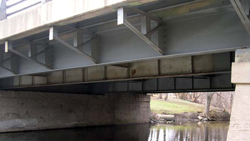
Plate girders are often used in structures having spans more than 15-20m. Normal plate girders are provided with intermediate and edge stiffeners, to utilize the post buckling strength of the webs. However, they are often expensive due to additional fabrication and welding. Moreover the detailing has to be proper-otherwise their fatigue strength may be reduced. Recent innovations like hybrid girders and corrugated webs coupled with the developments in automatic welding processes have made these girders economical, aesthetic, and faster to fabricate and erect. They offer as viable alternates to reinforced concrete beams in numerous types of long span structures.

Dr. N. Subramanian Consulting Engineer, Gaithersburg, MD, USA

Introduction

A plate girder is basically an I-beam built up from plates using riveting or welding. It is a deep flexural member that can carry loads which cannot be economically carried by rolled beams. Standard rolled sections may be adequate for many of the usual structures; but in situations where the load is heavier and the span is also large, the designer has the following choices, (Fig.1).
  • Use two or more regularly available sections, side-by-side.
  • Use a cover-plated beam; i.e. weld a plate of adequate thickness to increase the bending resistance of the flange.
  • Use a fabricated plate girder, wherein the designer has the freedom (within limits) to choose the size of web and flanges, or
  • Use a steel truss or a steel-concrete-composite truss.
Among the options available, the first is usually uneconomical and does not satisfy deflection limitation. The second option is advantageous where the rolled section is marginally inadequate. Therefore the real choice lies between the plate girder and the truss girder. Plate girders have a moment resisting capacity in between rolled I sections and truss girders. Truss girders involve higher cost of fabrication and erection, problems of vibration and impact, and require higher vertical clearance. For short spans (< 10 m) plate girders are uneconomical due to increase in connection cost and rolled I sections are the preferred choice.

Plate Girders

Innovations in Plate Girder Design
As stated earlier, plate girders are deep flexural members used to carry loads that cannot be carried economically by rolled beams. Plate girders provide maximum flexibility and economy. In the design of a plate girder the designer has freedom of choosing the component parts of convenient size, but has to provide connections between the web and the flanges. Instances where large loads and large spans occur are: gantry girders provided in industrial buildings to carry the rails for large capacity overhead traveling crane, deep girders provided in power plant buildings to support bunkers, railway bridges and many other applications in industrial and residential buildings. Plate girders offer a unique flexibility in fabrication and the cross section can be made uniform or non uniform along the length. It is possible for putting the exact amount of steel required at each section along the length of the girder by changing the flange areas and keeping the same depth of the girder. In other words, it can be shaped to match the bending moment curve itself. Thus a plate girder offers limitless possibilities to the creativity of the engineer.

It is a normal practice to fabricate plate girders by welding together three plates. In the past, plate girders were constructed by riveting or bolting, necessitating the use of angles to connect the web to flange joints (See next section and Fig.3). Since the introduction of highly automated workshops in the recent years, fabrication costs of plate girders have come down significantly. In the case of trusses and box girders, fabrication is still by manual means and hence their fabrication costs are high. Since nearly all plate girders constructed today are welded (although they may use bolted field splices), we will devote our attention to welded girders only. Moreover, welded plate girders provide more aesthetic appearance than bolted or riveted girders.

Innovations in Plate Girder Design
Figure 1: Options for beams of long spans to carry heavy loads (Not to scale)

The material in a plate girder is used optimally as the designer has greater freedom in varying the section as per the requirements. This has resulted in the extensive use of variable depth plate girders today. Thus it is possible to have tapered, cranked and haunched girders [see Fig.2(a)]. We can also have holes in the webs to accommodate the services. The designer may choose to reduce flange thickness (or breadth) in the zone of low applied moment, especially when a field-splice facilitates the change. Similarly in the zone of high shear, the designer might choose a thicker web plate. Alternatively higher grade steel may be employed in zones of high applied moment and shear, while standard grade steel (Fe 410) could be used elsewhere.

For longer spans plate girders compete very well economically. Similarly, when loads are extremely large, as in railway bridges, plate girders may prove to be economical even for smaller spans. The upper economical limit of plate girder spans depend on the following factors: (1) whether the bridge is simple or continuous, (2) whether it is a highway or a railway bridge, and (3) the length of the section which can be transported in one piece. In general, plate girders are economical for railway bridges of spans 15 to 40 m and for highway bridges having spans from 24 to 46 m. They may be very competitive for much longer spans, when they are continuous. They have been used in continuous bridge girders of spans in excess of 120 m.

The longest plate girder bridge in the world is a three span continuous bridge over the Save River at Belgrade, Yugoslavia with spans of 75–260–75 m. It has a double box girder cross-section varying in depth from 4.5 m at mid span to 9.6 m at the pier. Another notable long span continuous plate girder bridge is the Bonn – Beuel Bridge over the Rhine River in Germany which has a main span of 196 m.

Plate girders are also used in buildings when it is required to support heavy concentrated loads. Such situations may arise when a large hall with no interfering columns is desired on a lower floor of a multi-storey building.

Hybrid Plate Girders with High Performance Steel

Innovations in Plate Girder Design Innovations in Plate Girder Design
(a) Welded plate girder bridge in Basel, Switzerland (b) Two span, 107m long, curved plate girder for a viaduct, Denver, USA
Innovations in Plate Girder Design Innovations in Plate Girder Design
(c) Discovery Bridge over the Missouri River uses a Hybrid plate girder (Ref.17) Figure 2: Examples of plate girders

Hybrid girders, with different strength material in the flanges and web, offer a method of closely matching resistance of the section to the requirements (Fan et al, 2006; Veljkovic and Johansson, 2006 and Schilling, 1968). Fig. 2 shows some examples of plate girders. Fig.2(c) shows the Discovery Bridge over the Missouri River (US 81), designed by the Nebraska Department of Roads, completed in 2008. This bridge uses a Hybrid plate girder with Grade 345W steel for the web (yield strength =345MPa) and Grade HPS 485W steel for the flanges. The designation HPS denotes high performance steel, which was developed under a cooperative program between the Federal Highway Administration, the American Iron and Steel Institute, and the Department of the Navy in August 1994. The benefits related to HPS include enhancements in: weldability, toughness, corrosion resistance, ductility, fatigue and fire resistance, formability, and strength (Subramanian, 2010). These factors combined lead to construction elements of higher economic efficiency, ease of maintenance, and longer service life.

Types of Sections

Several possible plate girder arrangements are shown in Fig.3. Fig. 3(a) shows the simplest type of plate girder in which the flange plates are made of a pair of angles and they are connected to a solid web plate to form the plate girder. For larger moments, flange area can be increased by riveting/bolting additional plates, also known as cover plates, as shown in Fig. 3(b). When there are head room restrictions in buildings and larger depths of plate girders are not possible, box girders may be an option as shown in Fig.3(c). Box girders also provide greater lateral stability. If number of cover plates is to be reduced, the flange area can be compensated by providing plates inserted between the web and flange angles; see Fig. 3(d). These arrangements are sometimes adopted to keep the rivets/bolts both connecting flange angles and cover plates shorter. Figs. 3(e) and 3(f) show typical welded plate girders. The form shown in Fig. 3(e) is the most commonly used type of plate welded plate girder. Here, flange angles are not required and instead of using a number of cover plates, only a thick plate is used as the flange. As discussed already, a thinner cover plate can be used where lesser flange area is desired such as at regions away from the maximum bending moment section and the plates of different thicknesses can be joined by butt welding.

Innovations in Plate Girder Design
Figure 3: Types of plate girders

Early railway bridges in India and elsewhere (constructed during 1870-1900) were riveted plate girders, composed of angles connected to a web plate, with or without cover plates and having spans in the range of 15 m – 45 m. Most of the plate girder bridges constructed after 1960s are shop welded using two flange plates and one web plate to form a I- shaped cross-section.

Method of Design

The Indian code, IS 800:2007 Clause 8.4.2.2(a) says that the Simple Post Critical method (SPCM) can be used for webs with or without intermediate transverse stiffeners provided the web has transverse stiffeners at the supports.

Clause 8.4.2.2(b) of the code states that the Tension Field Method (TFM) may be used for webs with intermediate transverse stiffener, in addition to  the transverse stiffeners at supports, provided the panels adjacent to the panel under tension field action or the end posts, provide anchorage for the tension fields and if c/d >= 1.0, where c, d are the spacing of transverse stiffeners and depth of web, respectively.

Note that providing several stiffeners is expensive and time consuming and hence many designers and fabricators opt for SPCM with transverse stiffeners at the supports only. If the web thickness is very high (which will result in appreciable increase in weight), one may adopt the other method. TFM is usually applicable to thin webs with stiffeners at the ends and intermediate stiffeners. In order to avoid the intermediate stiffeners many firms in USA, Japan, Germany and other European countries now opt for corrugated or folded webs.

Suggestion to Code Clause

The equation for θ (inclination of the tension field) given in the code, in clause 8.4.2.2.(b), is actually the equation for è (slope of the panel diagonal). Normally, the value of θ ranges between θ /2 to θ. Eurocode-2 suggests a conservative value of θ /1.5 for θ.

The correct expression for width of tension field is given below

wtf = d cosθ-(c-sc-st) sinθ

Plate Girders with Corrugated Webs

To increase the shear capacity of large steel plate girders, shaped webs may be used; in this situation, the web plate is first cold formed with waves or corrugations usually parallel to the web depth and then welded to the flanges (see Fig.4 and 5). Corrugated webs increase their stability against buckling and can result in very economical designs, due to the use of thinner webs and elimination of fabrication and welding of stiffeners. Moreover, the corrugated web provides a higher resistance against bending about the weak axis. Although many types of corrugations are possible, trapezoidal and sinusoidal corrugations, as shown in Fig.4, have received the most attention. It has been estimated that these beams with corrugated webs may be 9 to 13% lighter than the conventional stiffened girders with flat webs.

Corrugated webs, though not yet commonly used for highway bridges in India have been used in several highway bridges constructed in USA, Europe and Japan. Girders fitted with corrugated webs have been used in the construction of Industrial buildings in Sweden, Germany, Austria and other European countries. Similar webs with reinforced and/or prestressed concrete flanges have been used for bridges in France. Recently, a new idea of combining tubular flanges with corrugated webs has been put forward (Wang, 2003).

Innovations in Plate Girder Design
Figure 4: Profile and geometric notation of girder with corrugated web

In USA the corrugated web beams were patented by Mr Young J. Paik who marketed it to builders in 1970s', and with the help M/s Sumitomo, a Japanese company, he started a company called PACO Engineering Corp., to manufacture and sell the product. The first prestressed hybrid box girder bridge was the Cognac Bridge, constructed in France during 1986 (Fan et al. 2006). More recently the Shinkai and Hondani bridges have been constructed in Japan (Fan et al. 2006). A summary of the research and development in girders with corrugated webs was reported by Elgaaly and Dagher (1990).

The results of studies on girders with corrugated web indicate that the fatigue strength of these girders can be 50% higher compared to girders with flat stiffened webs (Machacek and Tuma 2006). In addition to the improved fatigue life, these girders could be 30 to 60% lighter than the girders with flat webs and have the same capacity (Elgaaly and Dagher 1990). Thus, larger spans can be achieved with less weight. Moreover corrugated webs improve the aesthetics of the structure. Beams used in Germany for buildings have web thickness that varied between 2 and 5 mm and the corresponding web height–to–thickness ratio varied between 150 and 260. The corrugated webs of two bridges built in France were 8 mm thick and the web height – to – thickness ratio was in the range of 220 to 375.

While designing girder with corrugated webs, the following points should be remembered (Maquoi, 1992):
  • When the axis of the corrugations is perpendicular to the girder longitudinal axis, the web can not sustain significant levels of longitudinal direct stress, with the result only the flanges can be mobilized for the girder's bending resistance. Thus, the shear strength can be determined without consideration of moment-shear interaction. The ultimate moment capacity can be calculated based on the flange yielding, ignoring any contribution from the web.
  • The enhancement of shear strength is mainly due to an increase in the plate critical shear buckling stress, as a result of the corrugations; once the web buckles, large displacements and distortions occur and hence the post buckling strength can not be relied upon.
  • Compared to a plain web, a corrugated web with identical thickness can only be economical when its critical shear buckling load exceeds the ultimate shear load of the plain web. Fabrication costs, however, must be considered.
The corrugations increase the out-of-plane stiffness of the web and eliminate the use of vertical stiffeners. From the experimental results, it was found that failure in shear is usually due to buckling of the web and the failure in bending is due to yielding of the compression flange and vertical buckling into the web (Elgaaly et al. 1996, Elgaaly et al. 1997). The failure is sudden with no appreciable residual strength. For girders with tubular flanges and corrugated webs, the typical failure modes are local shear buckling of the web panel, yielding of the tubular flange and local plate buckling of the flange (Wang, 2003).

Innovations in Plate Girder Design
Figure 5 (a): Automatic welding of corrugated webs to the flanges and (b) An industrial building with columns and girders having corrugated webs (www.zeman-stahl.com)

Corrugated webs have been found to fail in shear by instability, and both local and global buckling modes have been observed experimentally. In theory, local buckling involves a single flat panel or ‘fold', whereas global buckling involves multiple folds, with buckles that extend diagonally over the entire depth of the web. Global buckling may be predominant for dense corrugation and local buckling for course corrugation. In experiments, however, failure modes that appear to have characteristics of both local and global buckling have been observed (Driver et al. 2006).

Plate stability theory can be used to predict the local shear buckling of corrugated webs (Lindner and Huang 1995 and Lindner 1998). A given fold (longitudinal or inclined) is assumed to be supported by adjacent folds along its vertical edges and by the flanges along its horizontal edges. The elastic shear buckling stress is given by

(Τcr,L)el= kL2E/[12(1 – μ2)(w/tw)2]}                   ..............(1a)

where,

kL = buckling coefficient, which depends upon the boundary conditions and the fold aspect ratio (w/h).

E = Young's modulus of elasticity, N/mm2

μ = the Poisson's ratio,

w = maximum fold width (maximum of the longitudinal fold width b and the inclined fold width c, shown in Fig.4), mm,

h = web depth, mm, and

tw = web thickness, mm

A small aspect ratio, w/h, minimizes the buckling coefficient k1 and is given by the following:

For the longer edges- simply supported and shorter edges - fixed condition,

kL = 5.34 + 2.31 (w/h) – 3.44 (w/h)2 + 8.39 (w/h)3 .............(1b)

when all edges are fixed, kL = 8.98 + 5.6 (w/h)2 .................(1c)

The above equation has been used by various investigators of corrugated web shear behaviour, to describe local buckling of individual fold.

Global buckling can be predicted by treating the corrugated web as an orthotropic flat web for which the elastic shear buckling stress is given by (Driver et al. 2006)

(Τcr,G)el = kG [(E tw0.5 b1.5) / (12 h2)] F (α,β)                   ...................(2)

where kG = global shear buckling coefficient that depends on the boundary conditions.

It can be taken as 31.6 for simply supported boundaries and 59.2 for fixed boundaries (Elgaaly et al. 1996)

F(α,β) = non-dimensional coefficient characterizing the web corrugation geometry

F(α,β)=√[(1+β)Sin3α/(β+cos α)].{(3β + 1)/[β2(β + 1)]}0.75 ...............(3)

where α = corrugation angle (See Fig. 4)

β = ratio of the longitudinal fold width b, to the inclined fold width, c.

A small value of β may lead to uneconomical design due to the large amount of web material required when the corrugations are deep. A large value of β may result in a low global buckling strength. Values of β are normally range between 1 and 2. The value of β is normally taken as 30° or 45°. Lindner and Huang (1995) suggest that the value of á should not be less than 30° for the corrugation folds to provide adequate support to one another along the fold lines to mobilize the full shear capacity. The parameter α not only influences the shear strength, but also fabrication and fatigue life. Lindner (1988) also studied the lateral torsional behavior of girders with corrugated webs and found that the torsional section constant J for a beam with corrugated web does not differ from that of a beam with flat web, but the warping section constant Cw is different.

Galambos (1998) suggest the use of the following equation for calculating the global elastic buckling stress

(Τcr,G)el = [(kG (Dx)0.25 (Dy)0.75)] / (tw h2)                   .................... (4)

where Dx = (q/s) E t3w / 12

Dy = E Iy / q

Iy = 2 b tw (hr / 2)2 + {t h3r / 6 Sin α}

The variables b, hr, q, s, and α are as shown in Fig.4.

When the elastic shear buckling stress (Τcr)el exceeds 80% of the shear yield stress Τy, the following inelastic equation can be used for both local buckling (with (Τcr)el taken as (Τcr,L)el from Eqn. 1) and global buckling (with (Τcr)el taken as (Τcr,G)el from Eqn.2 or 4).

(Τcr)inel = √[0.8Τy (Τcr) el] ≤ Τy ...................(5)

where Τcy is determined using the von Mises yield criterion as

Τcy = fy / √3                  ...................(6)

where fy = uniaxial yield stress of the web material, N/mm2.

Driver et al. 2006, proposed the following equation, which considers the effect of both local and global buckling in a single interaction formula

Τn = √[(Τcr,L Τcr,G)2) / (Τcr,L2 + Τcr,G2)]                  ...............(7)

The above equation, with lower bound values for kL and kG was found to provide a reasonable lower bound for the available test results.

Under static loading, the common practice of fillet welding the web to the flanges from one side only, was found to be adequate. Elgaaly et al, 1997 discusses about the lateral-torsional buckling of girders with corrugated web and Elgaaly and Seshadri provide information on the behaviour of these girders under partial compressive edge loading.

Summary

Plate girders are extensively used in a variety of buildings, especially when the span is larger than 15-20m. The developments in automatic welding processes have resulted in the fast and economic fabrication of welded plate girders. Moreover, the aesthetic appearance of these welded girders, have resulted in their proliferation. They offer a unique flexibility in fabrication and the cross section can be made uniform or non uniform along the length. They can be shaped to match the bending moment curve itself and hence offer limitless possibilities to the creativity of the engineer.

Recent innovations include hybrid girders (with normal steel for the web and High strength, high performance steel for the flanges) and girders with corrugated web and tubular flanges. The recent design of Discovery Bridge over the Missouri River, USA showed that such hybrid girder bridges are competitive than RC bridges (Traynowicz, and Sharp, 2009). The girders with corrugated webs have higher thinner webs (as their resistant to buckling is increased), higher fatigue resistance and are economical than girders with flat webs. They are also aesthetic and provide faster construction than ordinary plate girders with stiffeners or reinforced concrete beams. These innovative designs have been adopted in several countries for the construction of a variety of structures. The Indian code on steel structures does not contain provisions for their design and hence a few equations and references are provided, which may be quite useful in designing such innovative girders as an alternative to RC bridges and girders.

References

  • Driver, R.G., Abbas, H.H., and Sause, R., Shear behavior of corrugated web bridge girders, Journal of Structural Engineering, ASCE, Vol. 132, No. 2, Feb. 2006, pp. 195-203
  • Elgaaly, M., and Dagher, H., Beams and girders with corrugated webs, Proceedings of the SSRC Annual Technical Session, Lehigh University, Bethlehem, PA, 1990, pp.37-53.
  • Elgaaly, M., Hamilton, R.W. and Seshadri, A., Shear strength of beams with corrugated webs, Journal of Structural Engineering, ASCE, Vol. 122, No. 4, April 1996, pp. 390—398.
  • Elgaaly, M., and Seshadri, A., Girders with corrugated webs under partial compressive edge loading, Journal of Structural Engineering, ASCE, Vol. 123, No. 6, June 1997, pp. 783-791.
  • Elgaaly, M., Seshadri, A. and Hamilton, R.W., Bending strength of steel beams with corrugated webs, Journal of Structural Engineering, ASCE, Vol. 123, No. 6, June 1997, pp. 772-782.
  • Fan, Y-L, Mo., Y.L. and Herman, R.S., Hybrid bridge girders – A preliminary design example, Concrete International, ACI, Vol. 28, No.1, Jan. 2006, pp. 65-69.
  • Galambos, T.V., ed., Guide to Stability Design Criteria for Metal Structures, 5th ed., John Wiley, New York, 1998.
  • IS 800:2007, Indian Standard Code of Practice for General Construction in Steel, Third Revision, Bureau of Indian Standards, New Delhi, Dec. 2007, 143pp.
  • Lindner, J. and Huang, B., Beulwerte für trapezförmig profilierte Bleche under Schubbeanspruchung, Der Stahlbau, Vol. 61, No. 12, Dec. 1995, pp. 370-374.
  • Lindner, J., Grenzschu- btragfähigheit von I trägern mit trapaezförmig profilierten stegen, Der Stahlbau, Vol.57, No. 12, 1988, pp. 377-380.
  • Machacek, J. and Tuma, M., Fatigue life of girders with undulating web, Journal of Constructional Steel Research, Vol. 62, 2006, pp. 168-177.
  • Maquoi, R., Plate Girders, in Constructional Steel Design – An International Guide, Dowling, P.J., Harding, J.E. and Bjorhovde, R., ed., Elsevier Applied Science Publishers, London, 1992, pp. 133-173.
  • Schilling, C.G., Chairman, Design of Hybrid steel beams, Report of the Subcommittee 1 on Beams and Girders, Joint ASCE-AASHO Committee on Flexural Members, Journal of the Structural Div., ASCE, Vol. 94, No. ST6, June 1968, pp. 1397-1426.
  • Subramanian, N., Steel Structures: Design and Practice, Oxford University Press, 2010, 768pp.
  • Veljkovic, M., and Johansson, B., Design of hybrid steel girders, Journal of Constructional Steel Research, Vol. 60, 2004, pp. 535-547.
  • Wang, X., Behavior of Steel Members with Trapezoidally Corrugated Webs and Tubular Flanges under Static Loading, Ph.D. Thesis, Drexel Univ. USA, 2003, 212pp. http://idea.library.drexel.edu/bitstream/1860/98/10/wang_thesis.pdf
  • Traynowicz, M., and Sharp, D.J., Discovery Bridge over Missouri River, 2009, 10pp http://www.aisc.org/assets/0/1209478/1209480/1271820/9e281df6-b182-4029-a3b0-219f1913832b.pdf

NBMCW July 2011

Banner


Banner

Currently Online

We have 149 guests online

Alexa Rank


QR Code
Scan this QR Code to see this page on your phone
Copyright © 2010 NBM Media Pvt. Ltd. All Rights Reserved.